Are Your Generation Projects Ready for G98 and G99?
If you work in power generation in the UK, whether that is thermal, solar, wind, hydro or any of the other technologies. You are probably aware that there is a new standard coming into force called ENA G98 and ENA G99. These new standards will radically alter the design and planning process of all new generation projects, and make life much more challenging for schemes >1MW.
If you would like to know more about G99 and how it affects your business. Then please read on!!
ENA G99 and ENA G98 Overview
ENA G98 and ENA G99 are the two new standards coming into force affecting generating plants that will be connected to the UK distribution network from 27 April 2019. G98 replaces G83 and G99 replaces the G59 standard. These new standards will radically affect the connection and agreement process for all new solar, wind, battery storage, CHP and thermal generation plants that are planned for connection. The standard also now addresses integration of battery storage technology. This blog post is intended to discuss the technical aspects and changes to the connection process and does not delve into the commercial or legal implications of the changes.
As with the previous standards G99 is applicable to generators with a rating above 16A/ phase, and G98 applies to generators with a rating below 16A/phase. This blog post will focus on the G99 standard, as this is the more complex standard, and will affect the majority of Aurora’s Clients.
G99 – Who Will be Affected?
The companies likely to see the biggest changes and challenges are smaller companies who develop of medium sized generating facilities rated at more than 10MW, as these will face lot more complexity in the design process. Developers of sites rated between 1MW and 10MW will see some changes and new design issues and challenges, but there should be no fundamental shifts. Developers of smaller sites rated under 1MW should see minimal disruption.
The majority of the focus is, as expected, generators that operate in parallel with the grid. Short term parallel and standby units are excluded from the majority of all of the performance requirements. Practically, there is a lot of changes for dedicated generators, but for standby / emergency power, or equipment designed only for short term parallel operation, the standard remains very similar to the older G59 requirements.
Why the Change from G59?
So, first of all why the change? The simple answer is that the amount of embedded generation connected at 11kV, 33kV and 132kV has far exceeded expectations, and many of the larger traditional thermal generation plants are mothballed or nearing the end of their life. This has shifted how electricity is generated and distributed, and pushed the DNOs like UKPN, WPN, SSE, NPG, AuroraN and ENWL into a role where they need to actively manage their network in a way they haven’t needed to before. From a nationwide point of view to have an effective power generation network, it must be controlled actively with local generation matched closely to local demand to keep the electricity supply stable and within the necessary performance criteria.
The new rules have therefore been implemented to enforce new performance specifications on smaller scale generators connecting at theses lower voltages. The biggest changes affect projects that are greater than 10MW or are connected at 132kV – although in practice connecting a project <10MW at 132kV would be very unusual.
G99 – Generation Definitions
The new G99 standard brings with it lots of new definitions and acronyms. The most important of these are summarised below, they can be a little confusing as there are a lot of similar terms that overlap.
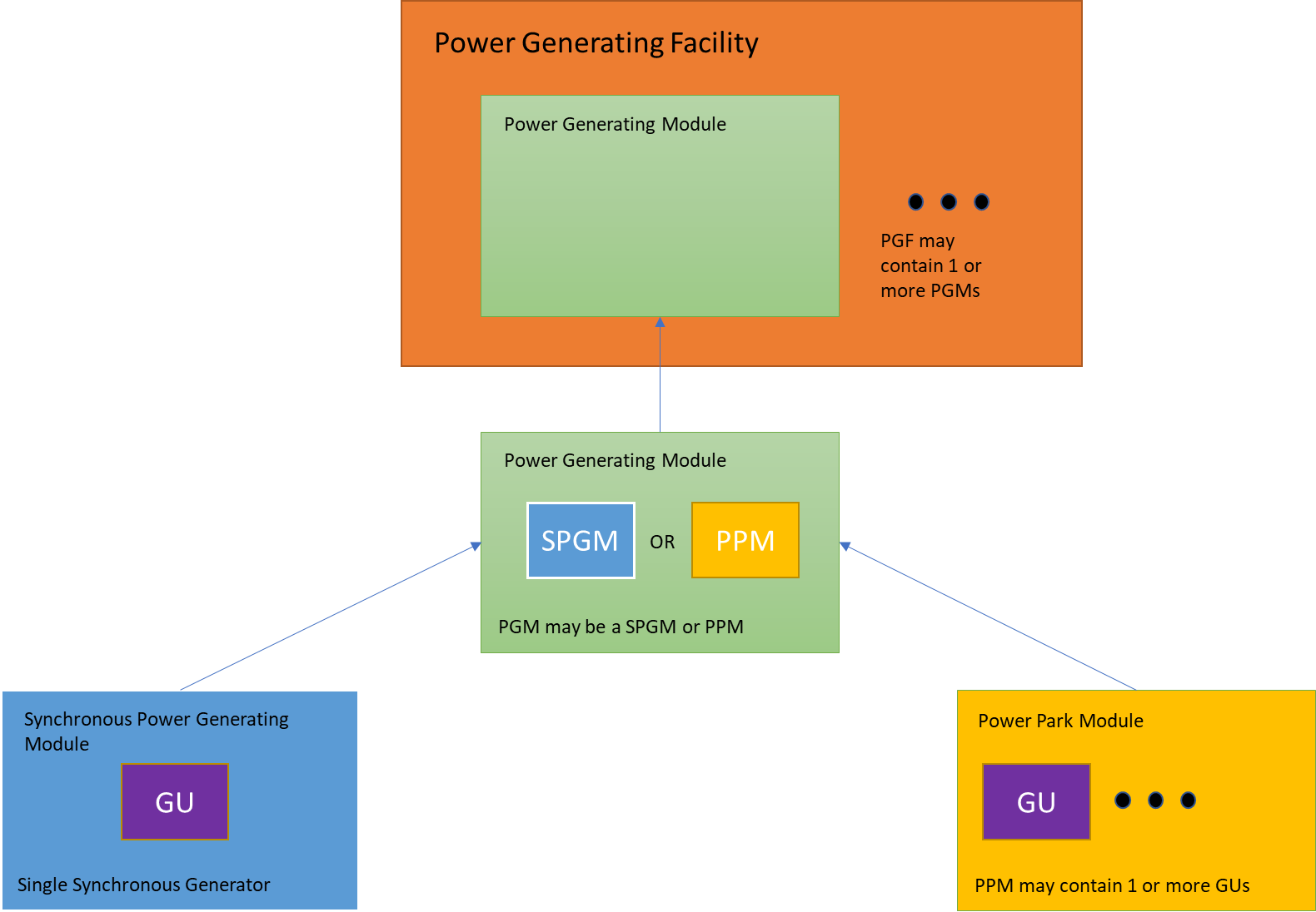
Power Generating Facility – A facility that is connected to the DNO network and contains one or more Power Generating Module.
Power Generating Module – A generating unit inside the Power Generating Facility. This can be either a Synchronous Power Generating Module or a Power Park Module.
Synchronous Power Generating Module – a generating unit inside the Power Generating Facility that (i.e. usually diesel engine, gas engine, gas turbine or steam turbine)
Power Park Module – A generating unit (or battery storage unit) that asynchronously generates power or is connected via power electronics (I.e. Type 4 wind turbines, batter storage units and solar inverters)
Generating Unit – Any unit that produces electricity.
G99 – Other Useful Definitions
Frequency Sensitive Mode (FSM) – A mode of operation (Type C and D only) where the generator should adjust their output in response to frequency deviations in order to help the grid recover.
Fault Ride Through (FRT) – The ability of the generator to remain connected to the grid during system disturbances such as voltage depressions.
Limited Frequency Sensitive Mode (LFSM) – A mode of operation, where the generators power output should remain constant despite frequency deviations.
Rated Capacity The normal full load capacity of a Power Generating Module, or of a Power Generating Facility, as declared by the Generator less the MW consumed when producing the same.
G99 Generation Functions and Roles
Generation that performs different functions, also have different requirements and is now split into three classes, depending on their role.
1 Designed for long term parallel operation with the Grid
2 Designed for short term parallel operation with the Grid (maximum of 5 minutes per month)
3 Designed for switched / standby power
Power Generation Module Types
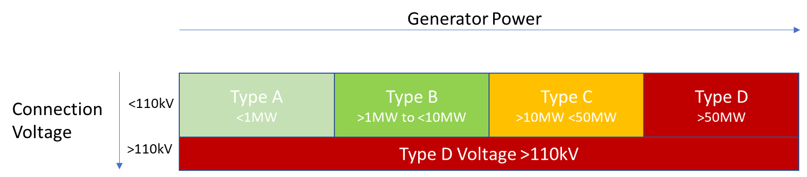
The first major change is that projects are now grouped into different Types of A, B, C and D depending on the total generation rating and its connection voltage. The standard contains a set of common rules, but then contains additional requirements for each generation Type. These are summarised below:
Type A – Generators <1MW and connected at less than 110kV
Type B – Generators >1MW and <10MW and connected at less than 110kV
Type C – Generators >10MW and <50MW and connected at less than 110kV
Type D – Generators >50MW or connected at a voltage greater than 110kV
In practical terms Type C and Type D are treated in a similar manner for design purposes. Type D connections are notifiable to National Grid and have additional Grid Code compliance issues and additional testing and witnessing requirements.
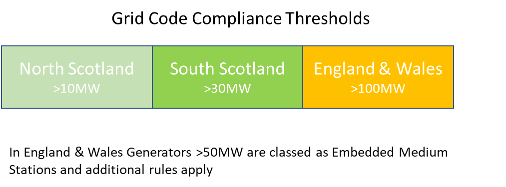
To further complicate matters, there are another set of thresholds, where if the overall Power Generating Facility, exceeds certain power thresholds based on its location (N. Scotland, S. Scotland or England & Wales). Then the National Grid Code will also apply.
G99 Generation Types
The next section talks about each of the generation Types in turn, and the key requirements of each class in general terms.
Type A Generators (Generators <1MW)
Type A generation systems will be very similar in design and application to the general requirements defined in G59, although some of these requirements have now been formalised in slightly more detail. The following list details some of the main requirements
- Performance & Control – Generators will now need an input signal from the DNO to stop generation, which must occur within 5s of signal receipt.
- Frequency Response – Generators must continue to operate for specified times, following a network frequency deviation
- Network Falling Frequency – Generator must retain constant power output down to 49.5Hz, after this point a linear drop off can occur of 5% to 47Hz
- Frequency Response (LFSM-O) – Generators should have the ability to reduce their power output in response to a rising frequency
- Voltage Limits and Control – should be able to provide constant power for a DNO network voltage deviation of ±10%
- Reactive Power Control – Generators should be able to operate between 0.95 lag and 0.95 lead PF
- Fast Fault Current Injection
Type B Generators (Generators >1MW and <10MW)
Type B generation systems will be broadly similar in design and application to the general requirements defined in G59. The big changes are that the manufacturers design and specification will need to improve, additional power system studies will be required to demonstrate compliance and there will SCADA interfaces to the DNO.
- Performance & Control – Generators will now need an input signal from the DNO that that can reduce their power from 100% to 0%
- Frequency Response – Generators must continue to operate for specified times, following a network frequency deviation
- Network Falling Frequency – Generator must retain constant power output down to 49.5Hz, after this point a linear drop off can occur of 5% to 47Hz
- Frequency Response (LFSM-O) – Generators should have the ability to reduce their power output in response to a rising frequency
- Fault Ride Through – Generators must remain connected and stable for two specific fault scenarios on the DNO network
- Voltage Limits and Control – should be able to provide constant power for a DNO network voltage deviation of ±10% and synchronous generators must have a flexible excitation system
- Reactive Power Control – Generators should be able to operate between 0.95 lag and 0.95 lead PF at registered capacity and operate for a wider range below full capacity
- Fast Fault Current Injection – Generators must be able to inject current into the system during fault conditions to help stabilise grid
- Operational Monitoring – DNO will be require installation of local SCADA / Telecontrol equipment to monitor performance
Type C and D Generators (Generators >10MW or Connected at >110kV)
Type C & D generation systems will see a large change and face a number of more significant design challenges. This will result in more power system studies being required to demonstrate compliance, complex controllers and interfaces to the DNO and an increased need for reactive power compensation equipment.
- Performance & Control – Generators will need full active control by the DNO
- Frequency Response – Generators must continue to operate for specified times, following a network frequency deviation
- Network Falling Frequency – Generator must retain constant power output down to 49.5Hz, after this point a linear drop off can occur of 5% to 47Hz
- Frequency Response (LFSM-O) – Generators should have the ability to reduce their power output in response to a rising frequency
- Frequency Response (LFSM-U) – Generators should have the ability to increase their power output in response to a falling frequency
- Frequency Sensitive Mode – Generators will require a full frequency based control system
- Fault Ride Through – Generators must remain connected and stable for four specific fault scenarios on the DNO network
- Voltage Limits and Control – should be able to provide constant power for a DNO network voltage deviation of ±10% and synchronous generators must have a flexible excitation system
- Reactive Power Control – Generators should be able to operate between 0.95 lag and 0.95 lead PF at registered capacity for all voltage between 95% and 105% and operate for a much wider range below full capacity
- Fast Fault Current Injection – Generators must be able to inject current into the system during fault conditions to help stabilise grid
- Black Start Capability – no specific requirements, but sites that have this capability should notify National Grid
- Operational Monitoring – Full real-time / time stamped data exchange with the DNO
G99 Summary Table
The following table summarises the main issues associated with each Generation Type.
| Generation Class | A <1MW and connected at <110kV |
B >1MW <10MW and connected at <110kV |
C & D >10MW <50MW and connected at <110kV or connected at >110kV |
| Performance & Control | Basic | Power reduction control | Active Control |
| Frequency Response – General | Basic | Basic | Basic, but ability to ride through frequency deviations |
| Frequency Response – Falling Frequency | Constant power to 49.5Hz then linear drop off | Constant power to 49.5Hz then linear drop off | Constant power output down to 49.5Hz, Power drop off linearly to a max of 5% at 47Hz |
| Frequency Response LFSM-O |
Requires ability to reduce power if frequency rises above 50.4Hz in linear manner | Requires ability to reduce power if frequency rises above 50.4Hz in linear manner | Requires ability to reduce power if frequency rises above 50.4Hz in linear manner |
| Frequency Response LFSM-U |
N/A | N/A | Requires ability to increase power if frequency rises above 50.4Hz in linear manner |
| Frequency Sensitive Mode | N/A | N/A | Site requires fast acting frequency controller |
| Fault Ride Through | None | Two specific cases where must remain stable for voltage depressions | Four specific cases where generator must remain stable for voltage depression |
| Voltage Limits and Control | Capable of operating with +/-10% network voltage deviation | Capable of operating with +/-10% network voltage deviation | Capable of operating with +/-10% network voltage deviation |
| Reactive Power Control | Operate within 0.95 lag to 0.95 lead | Operate within 0.95 lag to 0.95 lead at registered capacity and other power | Detailed reactive VAR capability required |
| Fast Fault Current Injection | N/A | Must be able to inject current into system during fault conditions | Must be able to inject current into system during fault conditions |
| Black Start Capability | N/A | N/A | Desirable – currently not clear |
| Operational Monitoring | None | DNO to install SCADA | Full comms interface to DNO |
| Notes | Refer to Section 11 of ENA G99 Not applicable to short term parallel generators and battery storage |
Refer to Section 12 of ENA G99 Not applicable to short term parallel generators and battery storage |
Refer to Section 13 of ENA G99 Not applicable to short term parallel generators and battery storage |
Examples
The following give a list of typical projects that would be covered by the rules, and which classification they would fall under.
Example 1: A 0.5MW Solar Farm connected at 11kV → Type A
Example 2: A 900kW Wind Turbine connected at 33kV → Type A
Example 3: A 1MW Solar Farm connected at 11kV → Type B
Example 4: A 4.5MW Wind Farm connected at 33kV →Type B
Example 5: A 10MW Solar Farm connected at 33kV →Type C
Example 6: A 20MW Battery site connected at 33kV → Type C but with reduced requirements
Example 7: A 30MW STOR site connected at 33kV in S. Scotland → Type C with Grid Code
Example 8: A 40MW Solar Farm connected at 132kV →Type D
Example 8: A 50MW STOR site connected at 66kV →Type D
Example 10: A 3MW CHP / generator added to an existing 11kV site to export power → Type B
Example 11: A 1MW CHP / generator added to an existing 11kV site to peak shave (no export) → Type A
Example 12: A new 2MW battery storage unit added to an existing 33kV site to export power → Type B, but with reduced requirements
Example 13: A new 10MW industrial plant connected at 33kV with a 500kW LV emergency generator → Non-specific (similar to G59)
Example 14: A new 5MW industrial plant connected at 11kV with 1.5MW of emergency generators designed to operate in short term parallel with the grid → Non specific (similar to G59)
Example 15: A 35MW CHP / generator added to an existing 33kV site in S. Scotland to peak shave and export → Type C with Grid Code Compliance
So What is the Impact To a Developer?
If you are a developer, you will probably be most interested in understanding how this translates into practical impact. Initially there is likely to be a lot of confusion and disagreements between the DNOs, and even different areas of the DNOs, so plan for extra time in getting approvals and energisation dates. Practically for design and costing purposes, Aurora thinks the following general statements summarise the main changes:
- Type A schemes (<1MW) – There will probably be little practical difference
- Type B schemes (>1MW to <10MW) – There will be a couple more studies to do, and the occasional need to either oversize some equipment or provide reactive power compensation
- Type C schemes (>10MW to <50MW) – There will be a lot more studies to do, equipment will need to be a higher specification, reactive power compensation equipment will often be necessary and there will be need for more complex communication and control equipment.
- Type D scheme (>50MW or >110kV) – Very similar to Type C schemes, but expect more interfaces and planning with National Grid
G99 Summary
Hopefully this article has given readers some understanding of the changes coming with the introduction of G99.In general life will be more complex, and as previously some certain types of projects and power ratings will be more viable than others. The general impact will be more study and design work is required in the early stages of a project and the DNOs will have to take a more active interest in the projects.
A word of warning, the G99 standard is very new and this article is based on Aurora Power Consultings’ understanding of the code. It is likely that once the code is in force and applied in detail, there will be many changes and clarifications on certain issues. So don’t assume that the standard is fixed! Lastly, this post is only intended as a brief guide to G99 and should not be regarded as exhaustive – if you would like to discuss your upcoming projects, please do not hesitate to get in touch.
We will be adding some more information about the G99 specific technical aspects of reactive power compensation, Fault Ride Through and Fast Fault Current Injection requirements, so please check back. G99 Overview (Detailed)