ENA G5/5 The New UK Standard for Harmonics
So as of 17th June 2020, G5/4 is now defunct and has been officially replaced with a new standard ENA G5/5. The old G5/4 standard was rather outdated and has been due for an update for a while. The new G5/5 harmonics standard is much more comprehensive, but it is big document, very technical and does not encourage casual browsing!
As with all new standards, expect a few tears and headaches before it fully beds in and everyone understands exactly what is required. At a practical level, I think Stage 2 assessments will be a different process but will generally result in fairly similar outcomes to G5/4 assessments. But, assessment for most larger inverters and systems (i.e. 200KVA and above) will need to be done with a computer simulation program like ETAP or DIgSILENT rather than with Excel.
For Stage 3 assessments, I think life will get a lot harder, I would recommend developers start giving themselves more time for assessment and to design in provision for inclusion of harmonic filters on larger (20MW+) systems. The last point is especially important, finding you need a filter at the last minute is a disaster if you have not planned for it, but if there is sufficient space in the substation and plot, and contingency in the contract, then it can be managed & mitigated to some extent.
At Aurora we have put together the first of two posts, on how the new standard will affect developers and designers. Stage 1 assessments are still reserved for LV connections, and generally only suitable for small loads. So, in this post I am going to talk about Stage 2 assessments, and how they work.
Stage 3 assessments get very tricky and I will discuss these on a separate post.
Key Changes in the G5.5 Harmonics Standard
There are a number of key changes associated with the new ENA G5/5 standard, and some important differences to recongise when compared with the old G5/4 standard, I have summarized these below in an easy bullet list format:
- The standard is now more aligned with IEC 61000-3-6
- There is more clear guidance on planning levels and compatibility levels, these are generally higher than the old G5/4 limits (a good thing)
- The harmonic level limits are given in terms of headroom, allocated on the basis of size of generator. This means that although the limits are higher, individual generators get less of them.
- Assessment is now potentially required up to the 100th harmonic – at the moment this is at the discretion of the DNO, so it may come in over the years rather than straight away.
- Higher order harmonics are now aggregated on an exponent law, rather than through simple summation.
- Stage 2 is now split into three sub-stages, and actively considers the background harmonic levels. This means that Stage 2 assessments will be a bit more complex and need direct information from the DNO.
- Stage 3 is still for all connections at 33kV and above or for failures at Stage 2
- specifically recommends adopting the practices given in CIGRE Electra 167
Stage 2 Assessment Overview
G5/5 Harmonic assessment at Stage 2 is still reserved for MV connections below 33kV, but has now split into three distinct stages depending on the size of the harmonic producing inverter / drive sizes. Small units of around 50kVA will fall under Stage 2A and should be able to connect in a relatively simple manner, and are assessed with a very easy ratio calculation. Slightly large units of around 50kVA to around 250kVA will generally fall under Stage 2B, but depend very much on the DNO system fault level, and now need to allow for as simple of the background harmonic levels. Larger systems will now need a more detailed assessment that considers the DNO background harmonic levels, and will need assessment of the incremental increase in harmonic levels due to the new inverters – practically this will mean the use of simulation programs to carry out this level of assessment.
Stage 2A
This is the easiest stage 2 approach, and sums the total powers of the harmonic sources ∑Sequ and compares this against the actual DNO fault level SPCC, against a predefined inverter ratings limits given in Table 21 (76kVA for a 6-pulse, 3 phase inverter) for an assumed DNO fault level of 60MVAsc. The formula for this is given below for ease of reference:
![]()
As always, let’s use an example to work it through; let’s assume that we have 3x 6-pulse standard inverters rated at 25kVA, that we are connecting at 11kV. In the first case lets assume the DNO fault level is 60MVA – our total aggregate load is 75kVA, the Table 21 limit is 76kVA and so we pass – although only just.
Next, if the DNO fault level is higher at say 100MVA, our allowable aggregate limits becomes 100/60 * 76kVA = 126.7kVA so we pass comfortably. Lastly, lets assume a worst case, where the DNO fault level is lower at 50MVAsc, our allowable aggregate limit becomes 50/60 * 76kVA = 63kVA and as our inverter total is 75kVA we would not pass at this level, and need to progress to Stage 2B.
There are two other things to note here. If the site uses dissimilar inverters, there is a slightly modified summation formula to use; and secondly, the limits are higher for drives with an active front end (673kVA) and for 12-pulse inverters (287kVA).
Stage 2B
This approach is similar to the previous stage, but this time also factors in the assumption that the limiting factor is the inverters output on the 5th harmonic. The calculations can still be done by hand easily, but now need to factor in the 5th harmonic planning level and background level for the 5th harmonic, which are used to give a headroom allowance. Then, as with Stage 2A, the total aggregate harmonic inverter ratings are summated and factored against the actual DNO short circuit level SPCC whilst taking into account the headroom allocation.
The formula for calculating the headroom is pretty straightforward and is given below for ease of reference:
![]()
So for an easy example, we know that the planning limit for the 5th harmonic at an 11kV connection is 3.0% (from Table 3 of G5/5), then let’s assume (for simplicity) the existing background harmonic level is 1.6%. From the above formula we can see that we have a headroom of 3.0% – 1.6% = 1.4%
Next, we use a slightly modified version of the equation in Stage 2A, which includes a factor to account for the 5th, this is again shown below for ease of reference:
![]()
To see how this is applied, lets consider the example from Stage 1A that failed i.e. where we had 3x 25kVA, 6-pulse inverters connected to a system with a fault level of 50MVAsc and using our headroom figure of 1.4% from above. So we can say that ∑Sequ = 76kVA (from the standard), V5headroom = 1.4% (which we calculated above), V5PL is 3.0% (from the standard), so substituting into the earlier formula we get:
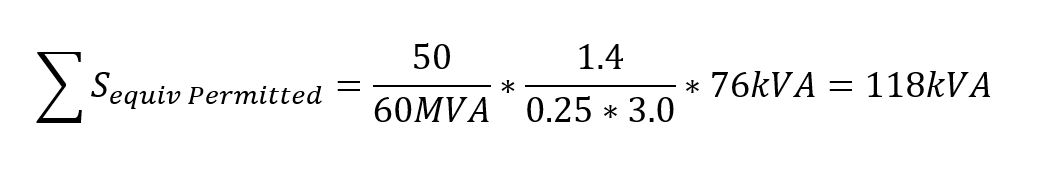
We can see that our connection is now allowable, based on some assumed headroom figures.
Now let’s consider the same scenario where the background harmonics are higher, and there is less headroom for the project. So lets assume that the background harmonic on the 5th is at 2.2%, our headroom is now 3.0% = 2.2% = 0.8%, so we can rework the main formula as follows:
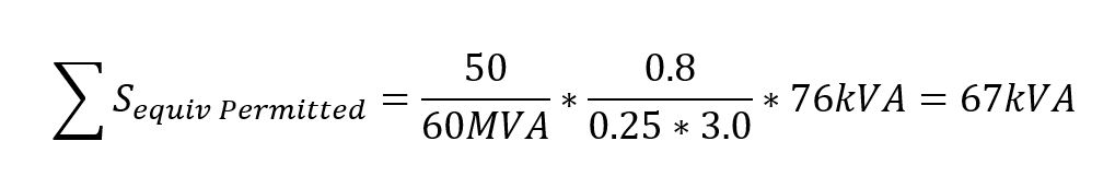
We can see that in this case, the assessment would fail and we need to move on to Stage 2C.
Lastly, lets see what happens, if there is a lot of headroom available, and a strong DNO network (i.e. high fault level). This time let’s assume the DNO fault level is 150MVAsc, and the background 5th harmonic is only 1.1%, our calculation would now become
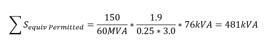
So we can see that we can add in quite a lot of inverter load onto the system and only use a simple assessment.
In summary, we can see that a lot of smaller projects that are not dedicated generation sites can probably be assessed using this approach, particularly if they are on a strong part of the system. As with Stage 2A, the rules are similar, but use a modified summation formula for dissimilar inverters and the limits are higher for 12-pulse inverters and drives with an active front end.
Stage 2C
This is where things now get a bit more complex, and where the majority of larger 11kV connected Solar PV, Wind and other disturbing loads will end up being assessed. At this point the assessment really starts to need a simulation package such as DIgSILENT, ETAP, PSS/E etc.. In theory it is possible to do the sums by hand or in Excel as used to happen in G5/4, it is not really practical to do so, and I suspect the DNO would challenge studies presented this way.
The Stage 2C process now diverges significantly from the earlier methods, and the process needs a number of definite steps to occur. Firstly, as with Stage 2B, we need to obtain the DNO fault levels, and a full set of background harmonics (as would need in Stage 2B). We then have to carry out a little maths to work out the harmonic impedance of the grid using some standard values, which we then load this into the simulation model as a simple frequency dependent characteristic of the Grid.
Next, we run a harmonic loadflow with the new inverters connected and the background harmonics switched off, and look at the voltage levels for Total Harmonic Distortion (THDv) individual harmonic order incremental increase (in %), and this gives us our incremental increase. We then rerun the harmonic loadflow study with the background harmonics on and determine the future harmonics levels (i.e. existing + new) and compare these with the planning limits. Its interesting to note that the standard currently requires just a check against planning limits, and not a check against a headroom allocation!
There is a really nasty sting in the tail, for Stage 2C. For most inverter drive wind turbines, PV plants or drives. The harmonic emissions depend on its loading i.e. you might find that at full power the 5th harmonic produces 20% current harmonic, but at 50% load this increases to 25% – what this means is that at part load, there is less current being injected, but the current is dirtier, than at full load. So G5/5 sneaks in this statement.
“For a Stage 2C assessment, it is the worst-case harmonic current emission at each harmonic order that shall be used.”
I personally think that this is unfair and unrealistic, as what it means (on paper at least), is that you have to take the worst harmonic % of each loading scenario into account during the assessment. So the inverters harmonics jump up at low loading conditions you have to take this into account, even though the inverter wont be producing much current.
G5/5 Harmonics Stage 2 Summary
As can be seen above, although it looks a bit messy the G5/5 harmonics approach to Stage 2 is actually pretty good, and doesn’t use the one-size-fits-all, approach of G5/4. In reality though, unless your disturbing load is very small, most developers are going to end up having to pay the DNO to provide background harmonics.
For industrial sites with good quality VSD with active front ends and on a strong network, or sites which have just added a small amount of solar or wind, then the assessment can often be done using the simple formulas shown above. For larger industrial sites with big VSDs or generation sites using Solar PV and Wind then a slightly more complicated study is needed; however, the good news is that in terms of cost, this probably wont be much more expensive or difficult than the old G5/4 approach. The bad news is getting harmonic data out of the DNO can take some time and may start leading to delays in projects, and there will be no such thing as a generic assessment any more, with each site need a more specific assessment.
As always if you have any questions please contact us, for further information.
In the next post, I will discuss the how a Stage 3 assessment works. This is where the standard gets a bit hairy and a lot of real headaches will occur and developers are likely to start facing problems and need to starting thinking about harmonic filters.