ENA G99 – Type C and D Plants and Studies Overview
This is a follow up post to my earlier one on G99 system studies. This time the post focuses on Type C and D plants (>10MW), which are a lot more challenging. The difference between Type C and D is fairly minor from a studies point of view, so I will cover both plants in the same post. The aim of this paper is to explain in practical terms the implementation and studies process for demonstrating compliance to the DNO. Type C and D plants generally get a pretty rough ride with G99 and are a big step up from type B plants. The below sections outline the basic requirements of each areas.
This post is written from the context of Solar PV plant, but equally applies to small Wind Farms. Plants with synchronous generators have very similar requirements to meet, but as their controllers (governors and AVRs) are more established, they generally have a much easier study and review process.
Reactive Power Flow
It is a requirement of the ENA ER G99, section 13.5, that power park modules must be capable of operating continuously within a certain power envelope. This is to ensure the required reactive power is either produced or absorbed to and from the connected grid. The site shall be capable of continuous operation whilst, maintaining the ability to operate within a power factor between 0.95 lagging and 0.95 leading. The Registered Capacity (RC) and power factor are measured at the Point of Connection (PoC). Generators should take any site demand such as auxiliary supplies and the Active Power and Reactive Power losses of the Power Generating Module transformer or Station Transformer into account, unless advised otherwise by the DNO.
For Type C and D generation plants, connected at > 33kV, when the site is operating at RC it must be able to meet the reactive power requirements, across a range of voltages at its Point of Connection (PoC), as indicated below in Figure 2‑1: Reactive Power Requirements at PoC >33kV – At Registered Capacity and for plants connected at ≤33kV then Figure 2‑2: Reactive Power Requirements at PoC ≤33kV – At Registered Capacity applies.
Furthermore, when the site is operating below its RC it must be able to meet the reactive power requirements, across a range of different output powers at its Point of Connection (PoC), as indicated below in Figure 2‑3: Reactive Power Requirements at PoC – Below Capacity.
What these slightly confusing looking diagrams mean that you need to be able to operate at 0.95 lagging and leading power factor even if the DNO voltage is away from its nominal value. Now the interesting thing with this is that for site that have a main step down transformer like a 132/33kV or a 33/11kV that has an On-Load Tap Changer will probably have an easier way of managing this, as the tap changer can maintain a more-or-less constant 1pu voltage on the main customer busbars. Sites directly connected at say 33kV or 11kV, are likely to have a few more problems.
There are two interesting things to note about this study. First, it is worth doing very early on, as a lack of reactive power capability is a common problem, and if its identified early it can be solved quickly – what you don’t want to do is find this last and then have to redo all the other studies. Secondly, you don’t need a dynamic model from the inverter manufacturer to run this study – just the inverter PQ capability diagram.
Figure 2 1: Reactive Power Requirements at PoC >33kV – At Registered Capacity
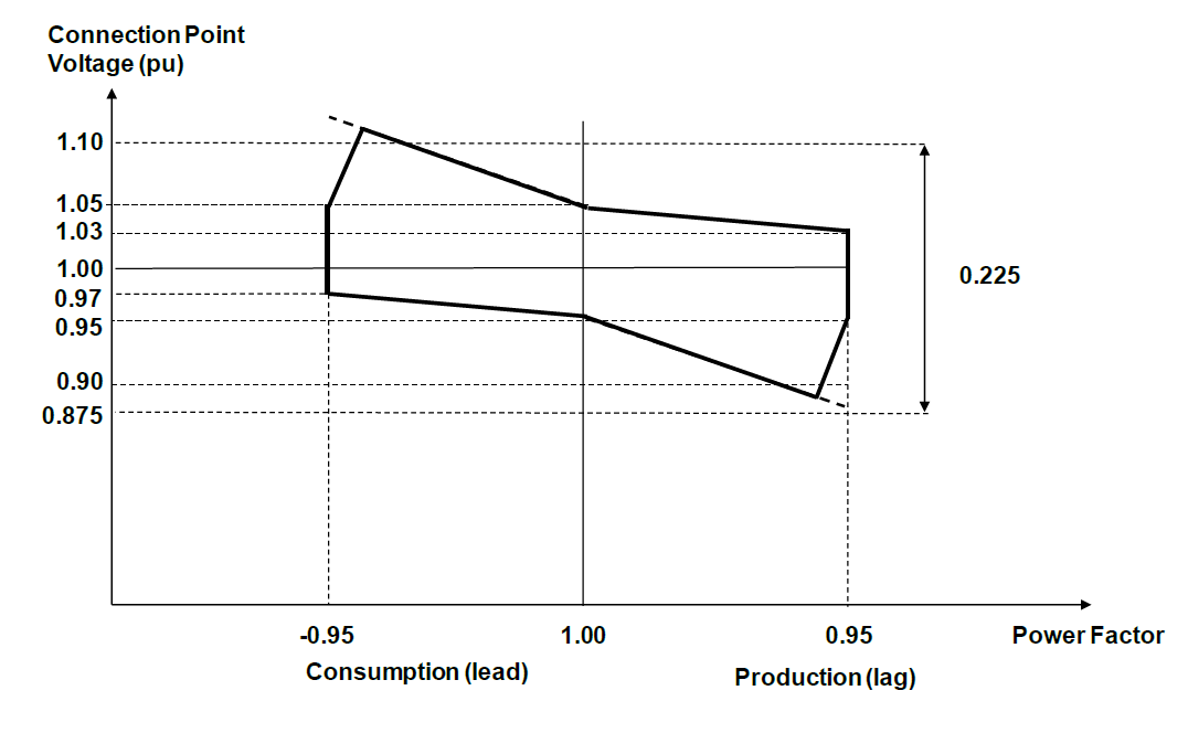
Figure 2‑2: Reactive Power Requirements at PoC ≤33kV – At Registered Capacity
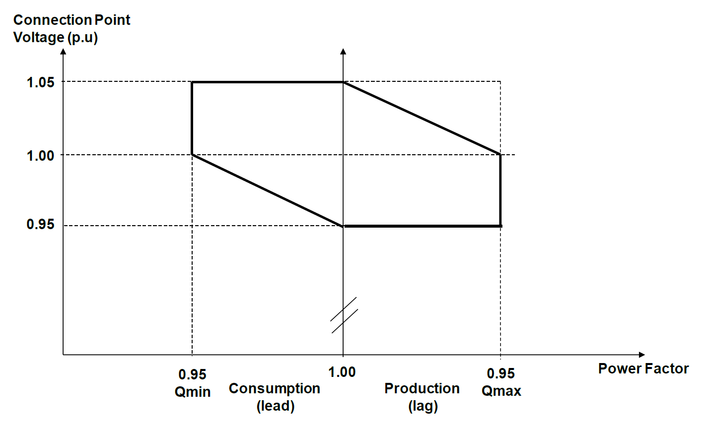
Figure 2‑3: Reactive Power Requirements at PoC – Below Registered Capacity

To demonstrate compliance with the reactive power flow ENA ER G99, Annex C 7.3.2 details four specific load-flow studies that must be performed to define the worst-case conditions for reactive power flow at Registered Capacity. The four loadflow studies performed are:
- Case 1 – When operating at full Registered Capacity and 1.03 pu voltage the site should be able to operate with a lagging PF of 0.95 (i.e. Exporting MW and MVAr)
- Case 2 – Case 2 – When operating at full Registered Capacity and 0.97 pu voltage, the site should be able to operate with a leading PF of 0.95 (Export MW and import MVAr)
- Case 3 – When operating at Minimum Stable Operating Condition and 1.03 pu voltage the site should be able to operate with a lagging PF of 0.95 (Export MW and MVAr)
- Case 4 – When operating at Minimum Stable Operating Condition and 0.97 pu voltage the site should be able to operate with a leading PF of 0.95 (Export MW and import MVAr)
Now the eagle eyed amongst you will have noticed that the four cases above, don’t actually correspond to the three Figures shown earlier. This is an omission in the standard that we have picked up and raised with the G99 committee and is currently being looked at – it isn’t really a problem for the 33kV or 11kV case, but is a headache at 66kV and 132kV. At Aurora we solve this issue by running various loadflow scripts to draw full capability diagrams of the site under study.
When the studies are being carried out, what we are therefore looking at is a) can the site meet the MW and MVAr requirements at its Point of Connection and b) can it do so without overloading equipment. To put this into context imagine the generation site is rated at 50MW, it should be able to deliver +50MW (P) and +16.5MVAR (Q) export and +50MW (P) and -16.5MVAr (Q) regardless of the DNO voltage.
Where things have got a little confused, is that a lot of DNO connection agreements and equipment are stated in MVA. So, this means that the MVA (S) rating of the above would need to 5.265MVA (S2 = P2 +Q2), it is important to factor this in at the start or it can mean some of the transformers, inverters and other equipment might be undersized. Note the (Q) value used above are rounded very slightly, so not exactly a true 0.95pf value.
Reactive Power Flow Stability
In addition, to the requirements given in above, it is also a requirement of the ENA ER G99, Annex C 7.4 that four specific time-based load-flow studies must be performed to define the worst-case conditions for reactive power flow at RC. These studies are intended to show that the generation unit can alter its reactive power flow contribution when the system voltage varies. In contrast to the steady state reactive power study, you need to have a fully working inverter model from the manufacturer to demonstrate compliance with this area of the G99 code. The four loadflow studies performed are:
- Case 1 – When operating at full RC and unity PF, apply a negative voltage deviation to cause the reactive power of the system to increase to maximum lagging (MVAr export)
- Case 2 – When operating at full RC and unity PF, apply a positive voltage deviation to cause the reactive power of the system to increase to maximum lagging (MVAr export)
- Case 3 – When operating at full RC and 95% of maximum lagging PF (MVAr export), apply a 2% negative voltage deviation to demonstrate output stability.
- Case 4 – When operating at full RC and 95% of maximum leading PF (MVAr import), apply a 2% positive voltage deviation to demonstrate output stability.
Fault Ride Through & Fast Fault Injection
It is a requirement of the ENA ER G99, section 13.3, that power park modules must be capable of riding through various network faults that result in a voltage disturbance on the electrical system. This is to ensure the inverters remain connected during a fault and can support the system recovery post fault. This can be shown below in Figure 2‑1 Type C Power Generating Module FRT Requirements.
Figure 2‑4: Type C Power Generating Module FRT Requirements
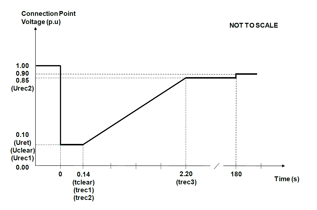
The FRT requirements exist for four types of faults 1) 3-phase faults, 2) phase-phase faults, 3) phase-earth faults and 4) phase-phase-earth faults. Depending on the type of plant a retained voltage must be defined to show that the overall system voltage does not collapse totally to 0. However, it should be noted that a retained voltage of 0.1pu, is not actually possible for an unbalanced phase-phase fault.
It is also a requirement of ENA ER G99, section 13.6, that during a fault the power park modules injects reactive power into the system, to support the voltage recovery. Injection of reactive power into the system should occur when the system voltage when the system voltage drops below 0.9pu, and is based on the pre-fault reactive current injected, and the retained system voltage (see above). This can be seen diagrammatically in Figure 2‑2 Type B Power Generating Module FFI Requirements.
Figure 2‑5: Type C Power Generating Module FFI Requirements

The Fast Fault Injection is not very clearly worded in the G99 standard, but in essence, it is a study that should be considered in conjunction with the Fault Ride Through (FRT) behaviour, and during the FRT study, it is necessary to check that the inverter (or generator) is producing reactive power as the voltage collapse occurs.
So, to demonstrate compliance with the above, ENA ER G99, Annex C 7.5 details four specific time based simulation studies (i.e. dynamic studies) that must be performed to define the system behaviour. The fault location, is set at the Point of Connection, and the four study scenarios performed are:
- Case 1 – balanced 3-phase fault.
- Case 2 – unbalanced phase-phase fault.
- Case 3 – unbalanced phase-phase-earth fault.
- Case 4 – unbalanced phase-earth fault.
The important thing to note with the above, is that for the simulation to be carried out it is essential to have a model of the inverter (or generator governor / AVR) that can be implemented within whichever modelling package the consultant is using (DIgSILENT or PSS/E etc.). Without this data from the manufacturer the study cannot take place.
Limited Frequency Sensitive Mode – Over Frequency
It is a requirement of the ENA ER G99, section 13.2.4 that power park modules must operate in a Limited Frequency Sensitive Mode (LFSM) and raise or lower their power output depending on the measured system frequency. This is to ensure the inverters modulate their power output in response to system power imbalances. specifically, for Type C generating plants, the implementation of LFSM-O is required, where the module must reduce its power when the system frequency exceeds 50.4Hz. The response of the system shall depend on the droop setting of the inverter, which shall be between the limits of 2% and 10%. This can be shown below[2] in Figure 2‑6: LFSM-O Response. Unless otherwise advised, it is assumed that a droop setting of 4% is used. It is noted that a droop setting of 2% will cause the inverters to unload more quickly than a droop setting of 10%.
Figure 2‑6: LFSM-O Response

To demonstrate compliance ENA ER G99, Annex C 7.6 details a single time based simulation study that must be performed to define the system behaviour, where the generation system is intentionally islanded from the grid via a load rejection scenario, to demonstrate operation of the module power active power reduction on rising frequency.
The simulation of this approach is complex, and described in detail in section C7.6, and basically states that an inverter-based generation plant, should be connected to the Grid (or equivalent large synchronous machine). This machine should supply an equivalent of the UK load, whilst the local PV Solar plant under test should include a ‘dummy’ synchronous generator ‘G2’ of nominal MVA rating (set at 1MVA for this project) operating at unity pf. A ‘dummy load X’ should be connected to the Solar PV site, the value of X should be selected to a value which the islanded system can contain the frequency rise to 52Hz and is typically the DMOL of the plant; the load value of ‘X’ should be increased by an equivalent load equal to the dummy ‘G2’ rating. Conceptually this can be seen below in Figure 2‑6 LFSM-O Load Rejection Test and Figure 2‑7 LFSM-O Load Rejection ‘G2’ Machine.
Figure 2‑7 LFSM-O Load Rejection Test
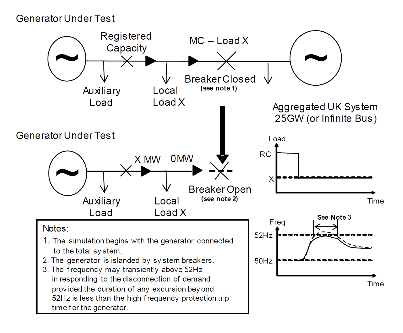
Figure 2‑8 LFSM-O Load Rejection ‘G2’ Machine
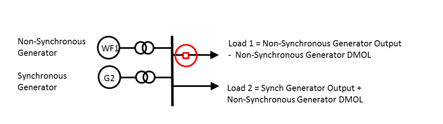
At Aurora we feel this requirement and test, can charitably be described as a bit ‘wooly’, as it doesn’t really appear to prove anything, and there are too many parameter to adjust, so we have escalated to the G99 committee and National Grid for a response. At the moment we have implemented the above scenario in DIgSILENT using an extension to the main Grid system. The system consists of an additional dummy synchronous generator ‘G2’ rated at XX MVA, a dummy load of (YY MW) equating to a DMOL of ZZ MW and XX MW equivalent for the ‘G2’ generator. The systems are then connected with common impedances of a very low value say R=0.01 on 100MVA base.
The two important things to note with the above, is that firstly, for the simulation to be carried out it is essential to have a model of the inverter (or generator governor / AVR) that can be implemented within whichever modelling package the consultant is using (DIgSILENT or PSS/E etc.). Without this data from the manufacturer the study cannot take place. Secondly, some ‘tunining’ of parameters is required to limit the frequency rise to under 52Hz.
Limited Frequency Sensitive Mode – Under Frequency
This is the complement of the LFSM-O study and is intended to show how a generator can ramp up, if it is being curtailed for some reason. It is a requirement of the ENA ER G99, section 13.2.5, that power park modules must operate in a Limited Frequency Sensitive Mode (LFSM) and raise their power output depending on the measured system frequency. This is conceptually similar to the LFSM-O mode described in the previous section and has a dead-band to 49.5Hz, on which the generation plant must start increasing its output if it is not operating at RC. It is of course noted, that in cases such as Solar PV and Windfarms, the plant may not be able to increase its output unless it is already under curtailment. The required response can be seen in Figure 2‑10 LFSM-U Simulation Response.
Figure 2‑9 LFSM-U Response
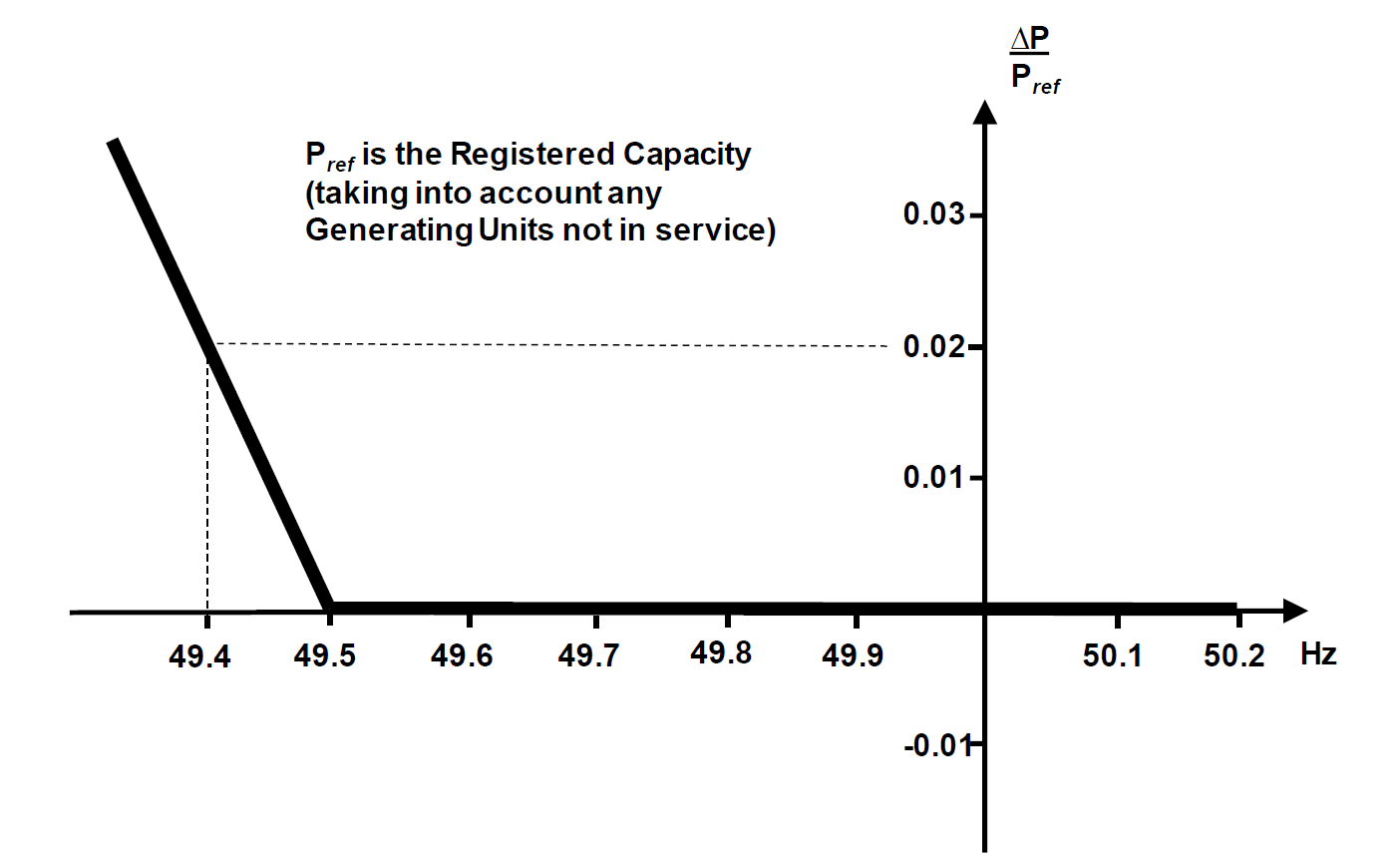
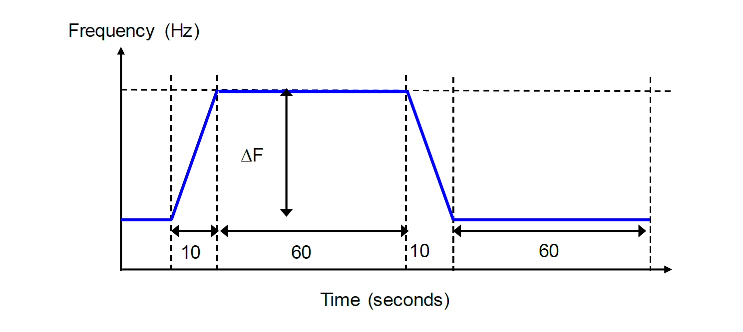
To demonstrate compliance ENA ER G99, Annex C 7.6 details a single time based simulation study that must be performed to define the system behaviour, where the system is initially operated at 80% of RC, and then the system frequency is depressed to 48Hz. During the frequency depression the power generating module active power increase should begin occurring at 49.5Hz, at a rate consistent with the droop setting.
Figure 2‑10 LFSM-U Simulation Response
The two important things to note with the above, is that firstly, for the simulation to be carried out it is essential to have a model of the inverter (or generator governor / AVR) that can be implemented within whichever modelling package the consultant is using (DIgSILENT or PSS/E etc.). Without this data from the manufacturer the study cannot take place. Secondly, the simulation package must be capable of altering the system frequency to show the generator response behavior.
Frequency Sensitive Mode – Under Frequency
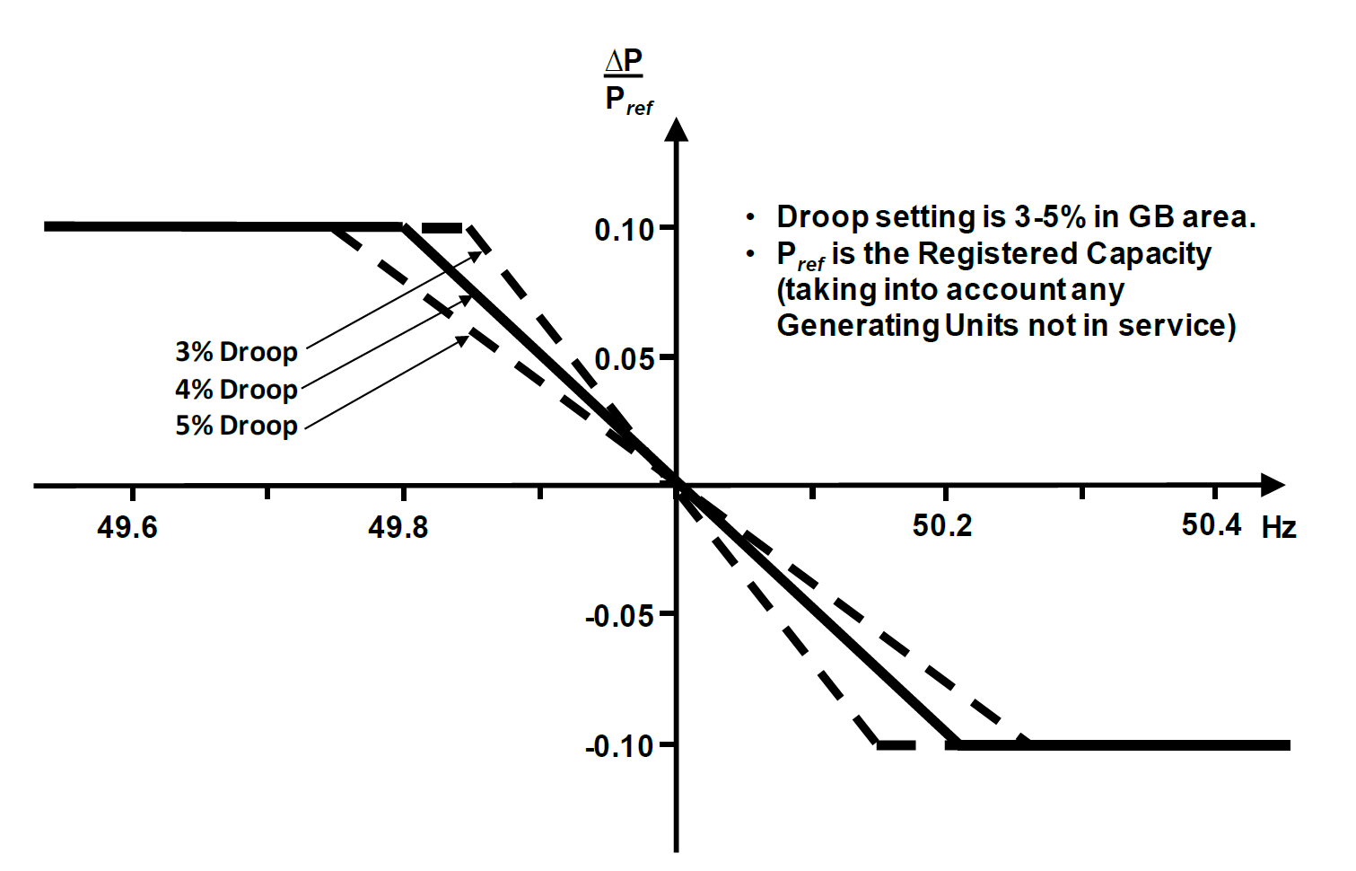
In addition to the requirements for LFSM operation detailed in the previous sections, it is a requirement of the ENA ER G99, section 13.2.6 that a Type C or D generator also must be able to operate in Frequency Sensitive Mode (FSM). This mode of operation results in the power generation module continually varying its output in accordance with the system frequency. When operating in FSM mode, the generator droop setting should be between 3% and 5%, and for analysis purposes is left at 4% (as with the LFSM setting), unless otherwise advised by the DNO or Client. This can be seen below in Figure 2-11: FSM Operation Response
Figure 2‑11: FSM Operation Response
To demonstrate compliance ENA ER G99, Annex C 7.6.5 requires that the test used of the LFSM-O operation is repeated whilst the generators are in FSM mode of operation, as discussed in the previous sub-section.
Summary
So, all those words and graphs apart what does all that mean for most developers. Let’s try and summarise the key points, into an easy bullet format.
- Type C and D plants are a lot harder than Type B plants. There is very little practical difference between Type C and D for studies purposes.
- For developers of plant based on synchronous generators, there are more studies to do, but the requirements in G99 are fairly easy to meet provided that everyone plans for them.
- However, to mee the studies the generator manufacturer must have a model available of their generator controller that can be slotted into the consultants modelling software (usually DIgSILENT or PSS/E).
- Most UK/EU generator manufacturers will heave readily available models for the above, but not all have – so developers need to make sure of this before committing to buy equipment.
- Reactive power is now a headache for Solar PV and onshore wind farms, as there needs to be sufficient capability to meet the active and reactive power limits. This means that plants must be designed such that the rating is based on the kW capability of a generator / inverter and not its kVA rating.
- The controls associated with LFSM, FSM and reactive power response are tricky for the inverter developers. For the first few years assume that the models provided by the developers will have lots of teething problems and that there will be some backwards and forwards needed to get them to work.
- Leave enough time to do the studies – they are no longer simple and are guaranteed to create odd results and problems.
As always, we hope you find the above useful. If you have any questions, please do not hesitate to get in touch with Aurora Power Consulting and we will be happy to help on your project. Understanding G99 and carrying out the studies is an essential part of the compliance process, and it is important not to leave it the last minute.
Legal Bits
The above is our interpretation of ENA G99, based on its current issue (presently Issue 1, amendment 6), and should not be taken as absolute advice. The images used in this article are taken from the G99 standard, but the rest of this article is the copyright © of Aurora Power Consulting and should not be reproduced without our permission.