This is a short post about the key ideas of 132kV design practices, too finish off the last of this series. In the UK, 132kV is the standard primary transmission voltage operated by the DNOs (it is also known as a sub-transmission voltage), the voltages above this point (275kV and 400kV) are full transmission voltages and run by National Grid (of SSE / AuroraN in Scotland). For the most part, 132kV is the province of DNOs only, there are some customers that take power in at 132kV but these are usually fairly uncommon. Consequently 132kV, has a abit of an air of mystery surrounding it in the UK, which isn’t really justified.
The aim of this post is therefore to explore some of the design issues and help clarify some of the points that must be considered.
The first and most important point to consider is if the 132kV substation will be an indoor type one, or an outdoor type design. These are electrically very similar, but are very different in terms of design approach, equipment needed and space requirements. The figures below show a typical 132kV indoor Gas Insulated Switchgear (GIS) and an outdoor Air Insulated Switchgear (AIS). For the majority of cases in 3rd party design, the switchgear will be indoor GIS type design, as outdoor AIS is too specialist and takes up a lot of space. At 33kV the cost difference between AIS and GIS is enough for DNO’s to be interested, as they have lots of substations but for private networks they will almost always use GIS – at 132kV however, there is a big cost difference between AIS and GIS. But, the space and hassle of outdoor 132kV switch-yards for private networks just doesn’t make sense in the UK, so most private networks will end up using GIS. Interestingly in the US / Canada and other large countries, AIS is much more more common.
For the rest of this post we will focus on GIS type designs.
The picture below shows a typical 132kV GIS switchgear line-up. In practice the ideas and technology is very similar to that of 33kV – however there are some important differences to consider. Discussed in a minute below
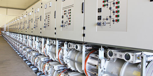
Figure 1 – A ‘Typical’ 132kV GIS Switchboard (ABB ELK type switchgear)

Figure 2 – A ‘Typical’ 132kV Outdoor Switchyard
So once the type of switchgear has been agreed, what are the issues that a 132kV design needs to consider? Some of the design approaches are actually very similar to 33kV and have a good degree of overlap – the good news with 132kV design is that switchgear is much more specialist, and there are far less options to choose from than at 33kV.
- 132kV switchgear will use a lot of protection devices, these are important substations feeding critical loads and so will often have quite complex protection schemes. Things to consider are
- Bubar protection schemes – high impedance with check zone or low impedance
- Will the IDMT protection schemes be a main and backup
- Does the protection need a watchdog signals
- It is also common to locate the protection relays on separate stand-alone panels in a different room for the GIS – this make its safer for operators to go and see what is going on.
- Does the substation need to be single busbar or double busbar (or even breaker and a half – although not usual even at 132kV)
- What inter-tripping schemes are needed? These substations often need to tie in to lots of other substations at the same / higher voltage.
- Cable terminations – 132kV cable jointing and termination is a big deal and needs careful consideration.
- What size cables are needed, and is there space to bend and terminate them? What type of termination kits will be used?
- Do the breakers need independent (2 different) trip coils
- Do you need to be able to expand the GIS in future?
- What sort of maintenance crane do you need for moving the GIS components around?
- How will the SF6 gas be handled, are there any alarms or leak detectors required? Will a ‘DILO’ cart be needed for topping up?
- How will the auxiliary AC & DC power supplies be provided? 132kV has a lot more auxiliary power requirements than 33kV or 11kV and they need planning carefully.
- Do the protection relays need any specific communication protocol or interface to a remote SCADA system?
- What are the interface points to the DNO, or other 3rd parties?
The above may seem like a long list of questions, but working through them in order will help the 132kV design progress and become defined. Usually during the initial design stages the design engineer will begin preparing a ‘Protection’ Single Line Diagram, which shows all of the key elements. Theses drawings then become critical in helping define the system and informing the switchgear manufacturer of what is required.
As always, if you would like to discuss your project. Please get in touch and let us help!