This is a short post about the key ideas of 33kV design practices. In the UK, 33kV is the standard primary distribution voltage, but for the most part is owned and operated by the DNO – some larger consumers or generating sites will receive a connection at 33kV if the local 11kV network cannot support their requirements.
Although 33kV is very common in the UK, its general restriction to the DNOs mean that the majority of design engineers will not have encountered 33kV before and may well be unfamiliar with the design practices. The aim of this post is therefore to explore some of the design issues and help clarify some of the points that must be considered.
The first and most important point to consider is if the 33kV substation will be an indoor type one, or an outdoor type design. These are electrically very similar, but are very different in terms of design approach, equipment needed and space requirements. The figures below show a typical 33kV indoor Gas Insulated Switchgear (GIS) and an outdoor Air Insulated Switchgear (AIS). For the majority of cases in 3rd party design, the switchgear will be indoor GIS type design, as outdoor AIS is too specialist and takes up a lot of space. For the rest of this post we will focus on GIS type designs.
 Figure 1 – A ‘Typical’ 33kV GIS Switchboard (ABB ZX type switchgear)
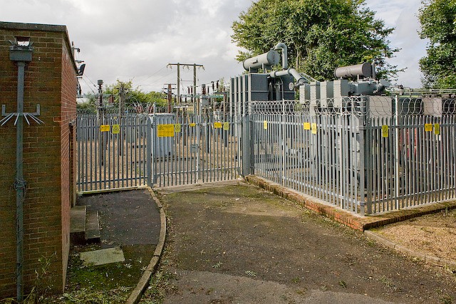
Figure 2 – A ‘Typical’ 33kV Outdoor Switchyard
So once the type of switchgear has been agreed, what are the issues that a 33kV design needs to consider? Some of the design approaches are actually very similar to 11kV and have a good degree of overlap – the good news with 33kV design is that switchgear is much more specialist, and there are far less options to choose from than at 11kV.
- 33kV switchgear will usually require a lot of protection devices – it is common practice to install differential protection on transformers and cables and distance protection on overhead lines, along with IDMT relays as backup protection. This needs a lot of careful thought and correct specification of CTs and VTs.
- Will the protection be mounted on the front of the GIS, or in a separate protection room?
- What fault rating and continuous current rating is needed for the switchboard?
- What protection relays are needed and what ratio CTs are required? Are any VTs needed?
- Will the 33kV bus-section be run normally open or normally closed (closed is usual at 33kV)
- What size cables are needed, and is there space to bend and terminate them? What type of termination kits will be used?
- Will the breaker design be based on vacuum interrupters or SF6 interrupters?
- How will the SF6 gas be handled, are there any alarms or leak detectors required? Will a ‘DILO’ cart be needed for topping up?
- How will the auxiliary AC & DC power supplies be provided?
- Does the switchgear need to inter-trip or interlock with any upstream or downstream systems?
- Do the protection relays need any specific communication protocol or interface to a remote SCADA system?
- What are the interface points to the DNO, or other 3rd parties?
The above may seem like a long list of questions, but working through them in order will help the 33kV design progress and become defined. Usually during the initial design stages the design engineer will begin preparing a ‘Protection’ Single Line Diagram, which shows all of the key elements. Theses drawings then become critical in helping define the system and informing the switchgear manufacturer of what is required.
As always, if you would like to discuss your project. Please get in touch and let us help!