P28 Studies
As the post title suggests, one of the common requests from DNO is for a ‘P28 study’, to assess the impact of disturbing loads on the network. The title ‘P28 study’ comes from the Electrical Networks Associate (ENA) standard P28 ‘Planning Limits For Voltage Fluctuations’.
This rather innocent sounding study, can in fact range from a brief study that is quite simple and may only take a day or two up to a very complex study that takes several weeks to complete. One of the most important issue to recognise is that a P28 study is not simply a formality and is often a significant obstacle in obtaining permission from the DNO to energise the equipment. If the P28 study limits are not met, then the DNO may insist on the use of expensive mitigating equipment such as Variable speed Drives (VSD), Pre-Insertion Resistors (PIRs), or even connection to a different voltage level. All of these issues, if encountered at the last minute can add significant cost and delay to a project.
Voltage Dips
In simple terms the P28 study is all about studying how the power system responds when loads are suddenly connected, or disconnected from the power system and the resultant voltage fluctuation.When a motor or transformer is energised for the first time, they can potentially draw a lot of power from the electrical network, which results in a voltage dip on the network due to the energisation transients. The size of this voltage drop depends principally on four main factors 1) The rating of the equipment to be connected, 2) the equipment design parameters, 3) the strength (fault level) of the network to which the equipment that is connected and 4) the point on the electrical cycle at which energisation occurs.
The reason for these limits is that voltage depressions on the network cause an increase in equipment heating (low voltage draws more current for the equivalent power) and can also create a flickering effect in any nearby lighting systems causing nuisance to other users. As the electrical network in most parts of the world is heavily interconnected, a user creating disturbances on one part of the network can cause real problems for other users on the same part of the network – which is why the limits are relatively stringent.
According to the ENA P28 standard, the maximum normal voltage dip is 3% for infrequent energisation (not more than 10 minutes) and 1% for regular energisation. For equipment that causes a voltage dip between 1% and 3% the number of energisations per 10 minute interval is limited to specific intervals.For transformer energisation, the rules are somewhat more vague but provided the transformer is only energised infrequently a voltage dip of up to 6% or even 10% may be accepted. It can therefore be seen that it is not only the size of the voltage dip that is important, but also the frequency of starting – for example a 75kW motor that starts once per day may be less problematic than a 37kW motor that starts and stops 10 times an hour.
Flicker
The other factor that is assessed in a P28 study is known as flicker. This concept is very similar to the concept outlined above – but certain types of equipment produce an amount of flicker even when operating, and so is not just limited to starting of equipment. This type of equipment is generally associated with large equipment that is controlled through an AC/DC inverter, or AC-DC-AC systems, and is therefore important in renewable plants (particularly solar). As with the voltage dip, calculation of flicker can be relatively simple if there are only a few small disturbing loads and quickly validated with a simple hand calculation, but can become complex where there are many large disturbing loads or inverters.
Example 1 – Transformer Inrush
One of the most common scenarios for a P28 study is to study the effect of energising a transformer. For most standard plants, this is not a real concern as transformers are only energised occasional, but for renewable power / generating plants, the issue is more significant as they are more likely to be switched due to the operation of the G59 relays.
Transformers are surprisingly complex items of equipment to analyse correctly, and to carry out an accurate study a model is required that takes into account the non-linear magnetic saturation properties of the transformer. This typically requires a model to be developed in EMTP, PSCAD or similar based on a detailed understanding of the transformers characteristics. The diagram below shows a modelling exercise carried out in EMTP-ATP for a small windfarm.
The first figure shows the model that was created in EMTP for the system under study. The exact modelling process used, is a little complex to discuss in this post, but essentially consists of a grid source, a pre-magnetisation circuit, time controlled switch and some measuring nodes.

Figure 1 – EMTP Model
The output of the study can be seen in the two figures below. Figure 2, shows the RMS voltage sag on the DNO network, which from simple maths can be observed as 2.18%. This falls within the allowable 3% limit of ENA P28, and provided the transformer is only energised on its own and with a 10 minute delay between other transformers the system is satisfactory. Figure 3 shows the individual phase currents decaying as the transformer magnetizes – these values are of less direct interest, but are useful as a check to confirm the peak phase current is in line with what would be expected of the transformer based on its declared inrush multiplier.
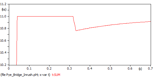 Figure 2 – RMS Voltage Sag
 Figure 3 – Inrush Current Decay
Example 2 – Generator (STOR) Trip
A more recent trend in P28 studies relates to the behaviour of small generation sites connected to the local DNO network. These generators can often be of a significant size, and tripping the generators (whether intentionally or due to the G59 relay) will create a corresponding voltage and frequency disturbance on the grid. The behaviour of the grid in this case is defined primarily by its system strength (fault level) inertia and the operation of the nearest grid transformer tap changer. These sorts of models are typically generated in Digsilent or ETAP (or similar), as they are ‘simpler’ (i.e. linear) The diagram below shows a typical modelling exercise carried out in Digsilent Powerfactory.
The first figure shows the model that was created in Digsilent for the system under study. The model is a simple representation of the system under study, using the parameters provided by the client, to accurately represent the system. The second figure shows the output curves generated by Digsilent for the RMS voltage and frequency deviation experienced by the system. For the size of the project, it is primarily the voltage deviation which is of interest, and the frequency deviation will be very small due to the grid inertia – however in small islanded networks, the frequency deviation is of much more interest.
It can be seen from the output curves, that the voltage deviation is almost exactly 3% and within the ENA P28 guidelines. This system is therefore acceptable, but some caution would be required and any changes in the system design parameters could be problematic.
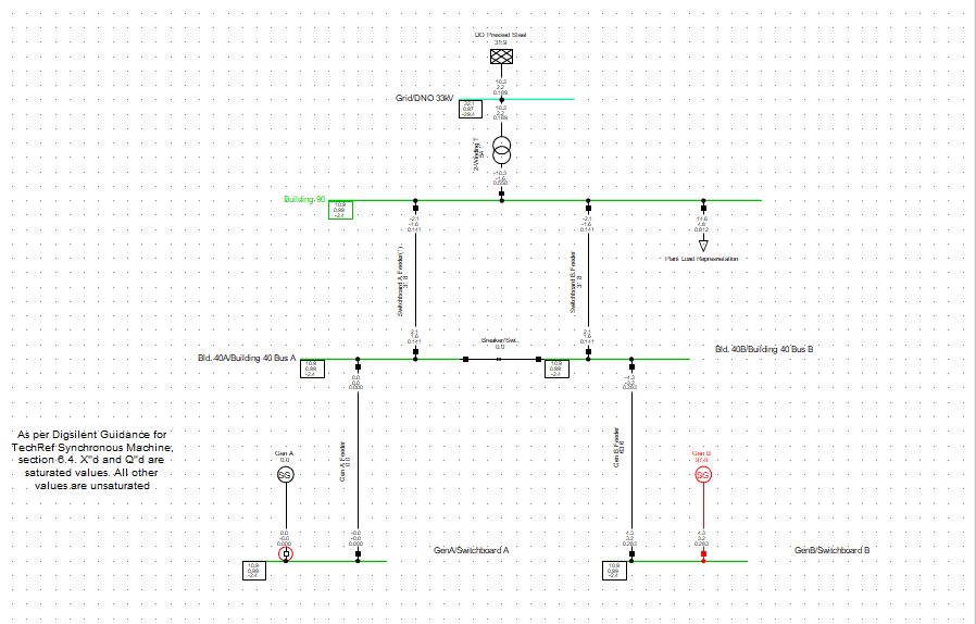 Figure 4 – Digsilent Model
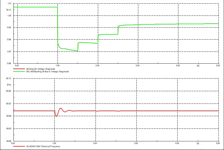
Figure 5 – Voltage and Frequency Deviations
Example 3 – Motor Starting
The last example is probably the most common scenario and affects most type of industrial plants that contain large motors. When the motor is started it draws a significant amount of power (around 6x its normal rating), for a number of seconds as it reaches its operating speed. This can lead to a significant voltage dip on the surrounding electrical network. The behaviour of the grid in this case is defined primarily by its system inertia and the operation of the nearest grid transformer tap changer. These sorts of models are typically generated in Digsilent or ETAP (or similar), as they are ‘simpler’ (i.e. linear) tha transformer inrush scenarios. The diagram below shows a typical modelling exercise carried out in ETAP.
The first figure shows a small part of the model that was created in ETAP for the system under study, and also includes the post-start, voltage levels in the system, which is a larger 3.3kV motor with a soft starter, connected to a unit transformer. The second figure shows the output curves generated by ETAP for the RMS voltage deviation experienced by the system.
It can be seen from the output curves, that the voltage deviation at the motor terminals is very significant at 11.8%, 4.6% at the upstream bus and 5.4% on a nearby LV MCC. The motor starting curve, is slightly distorted due to the operation of the soft starter, but otherwise acceptable. In this particular case the results were acceptable as the DNO was connected at a higher voltage and the voltage deviations experienced was within the acceptable limits. This system is therefore acceptable according to the standard, but caution would have to be exercised that the motor generated sufficient starting torque and that the nearby MCC did not trip on under-voltage .
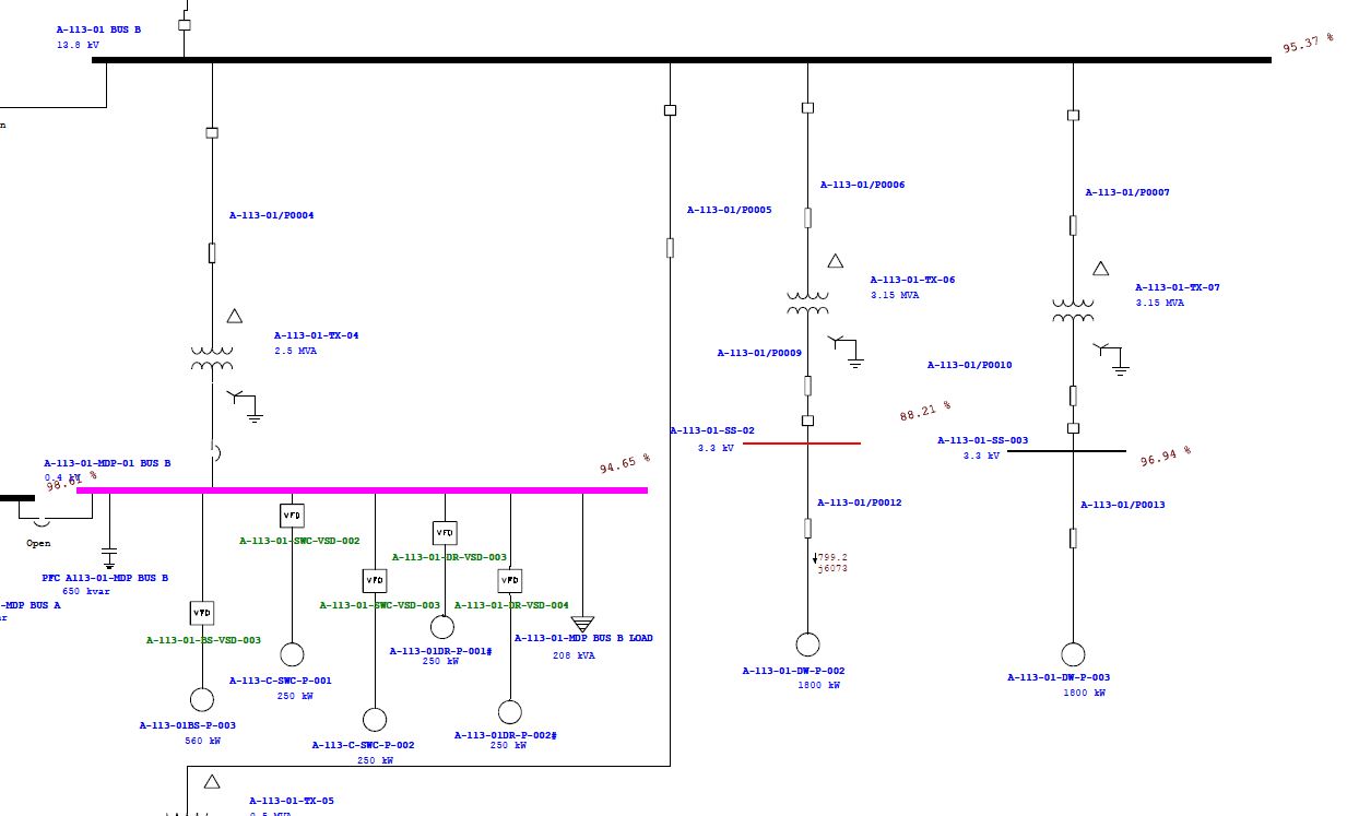
Figure 6 -ETAP Network SLD Extract
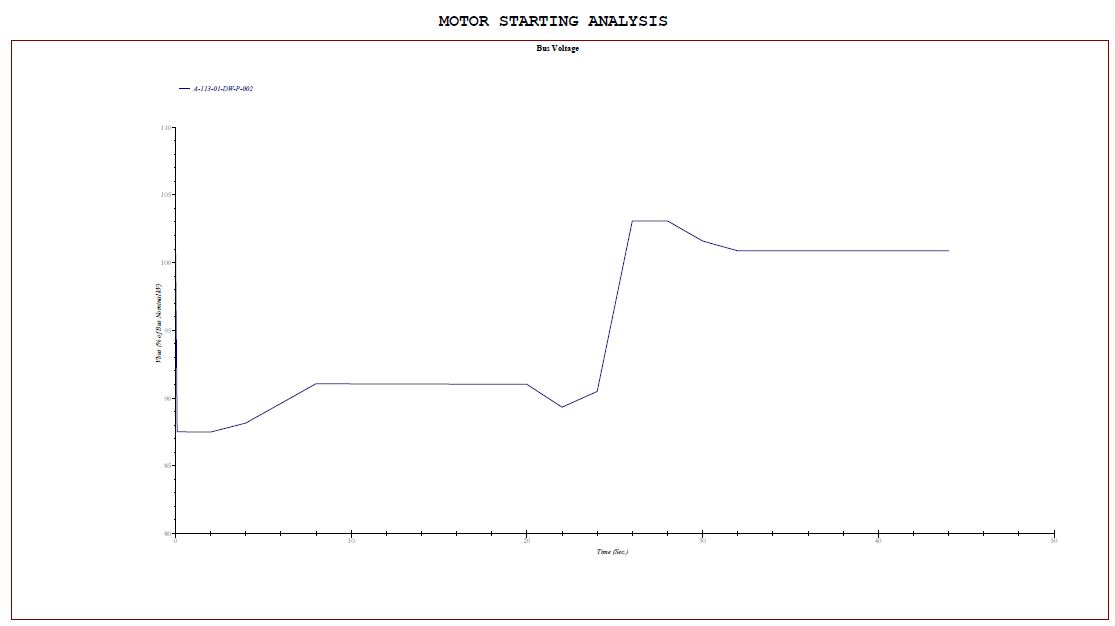
Figure 7 – Voltage Deviation
Summary
So, all of the above considerations aside – when do you need to consider carrying out a p28 study? In simple terms, it is generally when the DNO asks you to, but the typical cases where assessment would be needed are:
- When there could be a large motor that has to be started either Direct On Line, Star-Delta or with a Soft Start.
- Where there are medium sized motors that have to be started regularly.
- Distribution transformers that are energised semi-regularly for generating stations protected by a G59 relay.
- Plants that use a lot of arc welders or other short-term high-current equipment.
- Flicker caused by disturbing loads such as inverters for Type 4 wind farms (full AC-DC-AC converters) or PV solar arrays.
Lastly, please remember to carry out these studies early on in the plant design, as leaving the study to the last minute can create many problems when the results indicate that the P28 limits are exceeded.
Please contact Aurora to discuss your project requirements.