What is a Generator Export Limitation Scheme (ELS)?
At Aurora Power Consulting we have been approach by a number of Clients looking for help on Generation constraint system, Export Limitation Scheme (ELS), G100 and flexible connections. These terms all mean more or less the same thing, and the chances are that if your involved in Renewables or STOR generation in the UK you may have heard one of these terms. Similarly, if you have been considering adding an embedded generator to an existing site, or re-purposing a standby generator to reduce electricity costs, then an ELS might be needed. If you have wondered what these devices are all about and how it affects the viability of your scheme, then please read on.
Fundamentally, an Export Limitation Scheme, or ELS for short, is an intelligent controller, that is used to limit the power output of a generator, to prevent excess power being exported to the DNO network. The controllers can work in a number of different manners, but they typically either measure the power output at the site Point of Connection and ramp the generator power up/down to stay at the target setting, or they are triggered by the DNO to force a generator to reduce power output, if the DNO has a problem on their system. The requirement and needs for an ELS, is part of the UK strategy to have more dynamic network control and give flexible control over power generation and demand. The technical requirements for an ELS are given in the ENA G100 standard.
As may be expected, ELS systems are generally site specific and their use can be employed for a variety of reasons to constrain a generator. The three main reasons are discussed below, and in the rest of this post. 1) It is uneconomic for a generator to export to a grid 2) The DNO has a general system constraint and can only accept a reduced connection. 3) The DNO has a system constraint during abnormal operation.
Case 1: Simple Scheme with Zero Power Export
The first scenario is easy to understand, let’s suppose that we have a generator that is running as part of a larger industrial site, and is used in order to reduce the site load. The fuel source for the generator might be diesel, gas, or some other source, but it is not free, and so producing power has a cost. If the cost of fuel and the capital investment in a larger generator is excessive and the revenue gained from exporting electricity is minimal, then the site operator may not believe that power export is economic and thus intentionally prevent power export from occurring. The embedded generator is therefore just used for balancing the site load, to reduce electricity import to a low value.
Considering a specific case, as seen in Figure 1 below. The Site nominal load is 2MW, and the generator is rated at 2MW (for simplicity we are deliberately ignoring power factor at the moment), and the plant operator does not want to export power. As with any industrial plant, the site load will vary throughout the day and could be as low as 1MW and reach a peak of 2.2MW. The role of the ELS is to measure the power demand flowing into the site and then dispatch a MW setpoint to the generator. As peak demand, the ELC lets the generator run at full power, but as the site power demand drops off, the ELS issues a lower setpoint to the generator, so the net-power export is <0MW.
Practically as the load variations can occur quickly and the generator cannot respond instantaneously, the ELS will be designed to have a buffer / overshoot figure, so that should a plant load suddenly switch off power will not be exported. This would depend on the load profile, and various other factors but a figure of around 5% to 10% would be reasonable. The other point to note with an ELS system, is the need for a backup reverse power relay (ANSI Code 32P), this relay is designed specifically to measure the flow of power in/out of a site, if our zero power export limit of <0MW is reached then the relay issues a trip command to prevent the power from being exported. What the relays trips is to some extent optional, but it is usually better to trip the generator, rather than the site incomer!
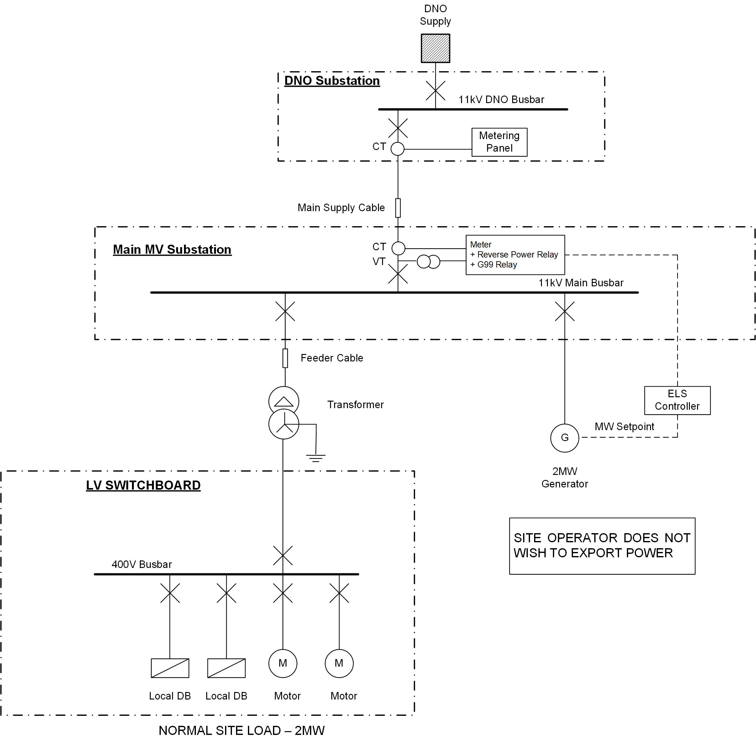
Figure 1: Simple Scheme with Zero Power Export
The above shows a classical, simple application of an ELS scheme in action. Figure 1 shows the generator and ELS connected at the MV switchboard, however if the generator was rated at 400V, it would be possible to install the ELS on the LV incomer and balance everything at the LV side.
Case2: Simple Scheme with Limited Power Export
The second scenario is almost identical to the first scenario, but in this case, the site operator might have a ‘free’ fuel source from inside the plant – this could be through burning waste, a heat recovery system or similar. So, let’s consider a scenario where the site operator has enough fuel to drive a 5MW generator, and under a normal operating case the site draws between 3MW and 1.5MW of power, depending on how active the plant is. This gives a power balance of between 2MW and 3.5MW that can be exported to the grid. This scheme can be seen in Figure 2 below.
However, once the developer has come up with the scheme, they speak to the DNO who advises that they have a system constraint in the area, and can only accept 2.5MW of power based on their existing configuration. The DNO advises that upgrading their system to accept 3.5MW of power would cost several million, and take a number of years, and would make the scheme unviable for the developer.
This is where an ELS can help. An ELS is designed and installed, where the ELS measures the site power demand and then limits the fuel flow into the generator reducing its MW output down to the maximum export value of 2.5MW value that the DNO has imposed. So, under heavy loading conditions, the generator can run at full power, at light load conditions, the generator MW output is constrained to prevent the site from exceeding the limit.

Figure 2: Simple Scheme with Limited Power Export
The above is very similar to Figure 1, and shows a classical, simple application of an ELS scheme in action, as with the first scenario the generator and ELS is connected at the MV switchboard; however if the generator was rated at 400V, it would be possible to install the ELS on the LV incomer and balance everything at the LV side. As with the first case, a backup reverse power relay is installed on the incomer to prevent excess power export – but this time it is set to operate at -2.5MW.
Case 3: Dedicated Generation Scheme with Flexible Connection
The third scenario is very different to the first two, and is more usually seen on much larger systems, where there is a significant amount of generation export power. In this case the constraint depends on the DNO network configuration, who in certain circumstances such as an outage, can only accept limited power. To understand this limit, let’s consider a fictious case where a developer is planning a 30MW STOR generation site planned for connection at 33kV, via a loop-in and loop-out connection. This can be seen in Figure 3 below.
Suppose that when the DNO system is operating in normal configuration it can accept the full 30MW of generation, but if the DNO has an outage (either planned or unplanned) it can only accept 20MW. The developer can pay for the full upgrade of the DNO system to support the 30MW rated capacity, or the developer can reduce the site capacity down to 20MW, with an impact to the developer’s revenue calculations.
An alternative approach is to use an ELS so that when the DNO system is operating in an abnormal condition, the scheme power output is turned down to 20MW and the system constrained. This is sometimes called a flexible connection and is good compromise of avoiding expensive upgrades of the DNO network, whilst allowing the full capacity of the site to be utilised for most of the time. In this mode of operation the ELS is measuring power output at the incomer, but its limitation mode is also triggered by the DNO, either as a remote SCADA command, or perhaps as a simple monitoring of the two 33kV incomer breaker status indication.
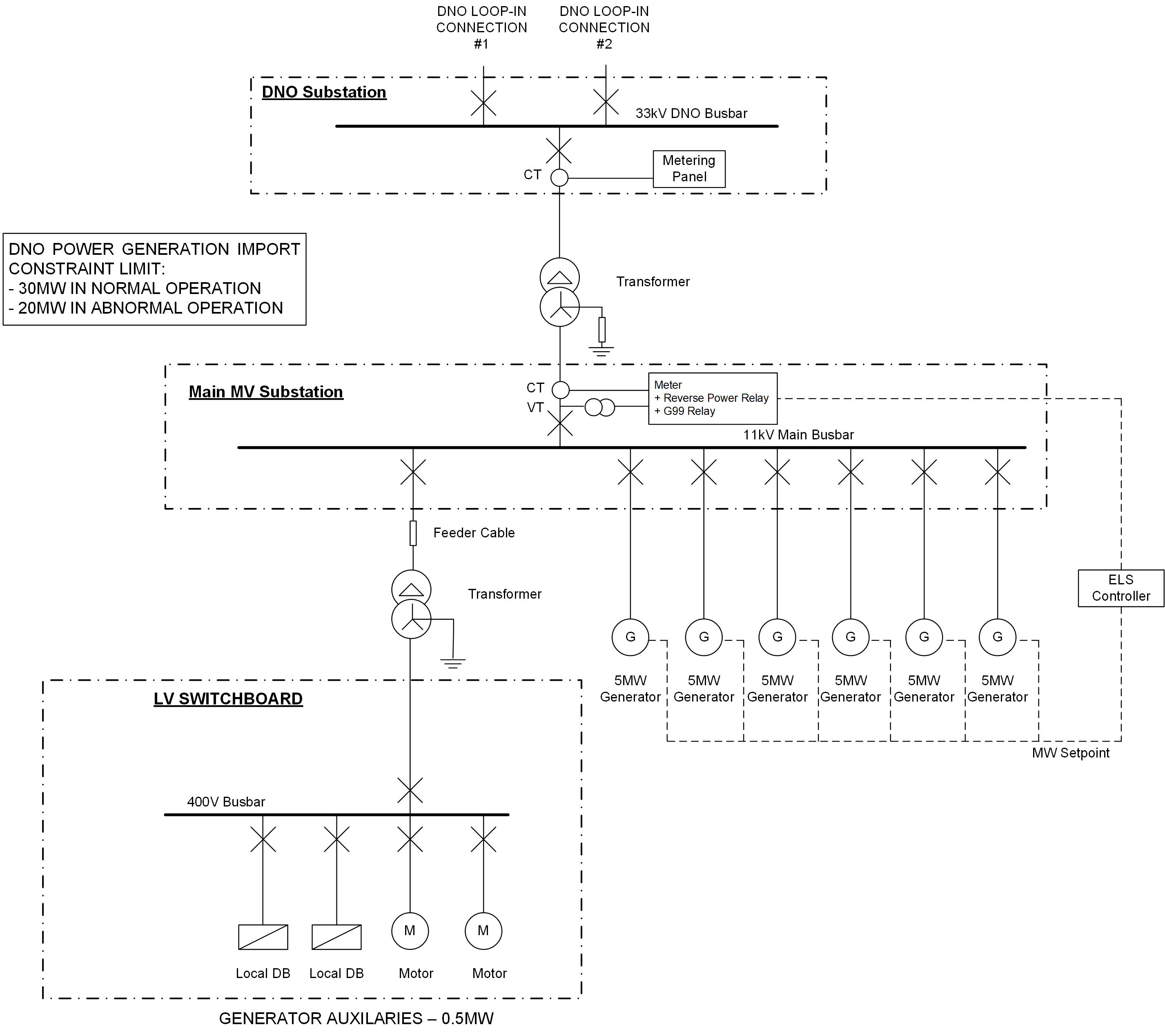
Figure 3: Simple Scheme with Limited Power Export
In this scenario, the ELS may be in the customer substation or be installed as part of the DNO system – this will depend a little on the DNO and overall system configuration. As the ELS is controlling multiple generators, it will generally be a more sophisticated unit than the ones discussed in the other scenarios.
The important factor on deciding whether this type of scheme is viable from the developer’s point of view is a) how often will the constraint occur, and b) when will it occur. Considering our STOR scheme, if the constraint occurs often, and in high demand winter months, then major revenue could be lost, but if it is infrequently, and only in the low demand summer months then it could be viable.
Summary
The above descriptions of the differing roles of how and why an Export Limitation Scheme may be deployed on a new development and its potential roles and benefits. The important thing for a developer to recognise is that whilst an ELS may seem like an unnecessary constraint, it is actually a tool that can help a developer make a scheme more economically viable, by optimising the generation strategy or reducing the need for major DNO upgrade costs. The Developer should be careful however to understand the constraints that the ELS imposes, as factor this into their economic modelling. An ELS can also be deployed when adding a generator to an existing brownfield site, or re-purposing a standby generator for peak shaving, but this process is more complex, because of the site tie-ins. We will discuss the further in a separate blog post.
If you would like to understand more about the role and use of an Export Limitation Scheme and how they can be deployed on your project, please do not hesitate to get in touch with Aurora Power Consulting, and we will be happy to discuss your project further.