The Short Circuit Study
IEC 60909 / ENA G74
An IEC 60909 / G74 short circuit study refers to the process of determining the fault levels (commonly called short circuit levels) in an electrical power system. The IEC 60909 standard for short circuit calculations in three phase AC systems, is a well known and commonly used standard, while the G74 standard refers to a UK Electricity Networks Association (ENA) standard, that is aligned with IEC 60909. The actual G74 standard was originally developed as an alternative to the IEC 60909 (or 909 standard as it was then), to provide more accuracy for determining fault currents, because the UK operators considered the IEC 60909 standard to be too conservative, and calculations would potentially provide inaccurate results.
In practice the difference is centred around the IEC 60909 use of voltage ‘C’ factors – these ‘C’ factors are used to define the pre-fault voltage, while the G74 approach is based on using a calculated pre-fault voltage based on a loadflow study. The G74 approach usually results in lower fault levels, as the pre-fault voltage is usually around 1.0 pu, while the use of ‘C’ factors creates slightly higher results.
The current position is now somewhat unusual, as the last version of the G74 standard was issued in 1992, and the IEC 60909 standard has been updated and reissued several times – including most recently 2016; this leads to a scenario where the G74 standard looks rather out of date. To further complicate matters, the latest versions of the IEC 60909 document include more sophisticated / robust ways of calculating fault levels and managing new technology types such as Solar (PV) and Wind Turbines – that were not covered in earlier versions of the document.
There are two other factors that confuse matters further. Firstly, the G74 standard is UK specific – so it is not well recognised elsewhere in the world. Secondly, power system simulation packages have made great progress in the last 15 years – and almost all (apart from IPSA) are made outside of the UK.
When considered together these two issues create a problem for studies engineers wishing to carry out a G74 study, as it is not easy to do so. What is the solution? There are basically three approaches: 1) Carry out the study to the latest version of IEC 60909 as you would normally, and provide some explanatory notes in the report to justify the position. 2) Carry out the study to IEC 60909 and set the voltage ‘C’ factors to 1 or 3) Carry out a short circuit study that does not use voltage ‘C’ factors, and is based on loadflow pre-fault voltages – this approach is however very dependent on the software package available to an engineer.
Understanding a Short Circuit
A short circuit is a faulted condition in the electrical network, that must be detected by the protection relays and cleared as quickly as possible. During a fault, a very high level of current will flow in the network, which stresses the system. if the fault is not cleared quickly it can lead to a rapid escalation leading to trip of upstream systems and widespread power loss.There are many different types of fault that can occur in the system, but in a short circuit study there are two that are of primary interest – 3-phase faults and phase-earth faults. Three phase faults are relatively uncommon, but do happen, and are usually very destructive and lead to major damage and power loss; phase-earth faults are much more common (it is believed that 90% of faults are phase-earth), and are often caused by failures of cable joints and terminations.
Regardless of the fault type, the fault current will behave in a reasonably predictable way, as shown by the following figure. There are several components to the fault current, all of which are equally important. The most commonly discussed value is known as the steady state current I”k also known as the break current Ib (the two are actually slightly different), and when engineers talk about fault current this is usually the figure they mean and how the ratings of switchgear and circuit breakers are defined. The second value is the peak short circuit current, and is (as the name implies), the maximum value of current that will flow in the first cycle – this figure is important for switchgear designers as it defines the maximum electro-mechanical stresses on the the switchgear and busbars. The third figure is the DC offset of the fault current, and is a slightly more complex subject. In simple terms this causes the fault current value to be offset to a higher value than it actually is and places an increased duty on the switchgear and circuit breakers. This is actually caused by a very high X/R ratio on the network, but fortunately this sort of situation is only usually encountered with generating plant, or very large grid transformers. For a more detailed oerview of DC component, please have a look at our technical paper on asymmetric switching duties here.
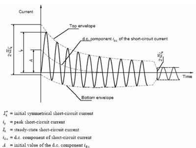
Figure 1: Fault Decay
It can also be observed from the Figure that the the fault current decays rapidly as the DC current offsets and then reaches a much smaller value later. This figure is slightly simplified, but is intended to show the decrease as the synchronous generators in the system move from the sub-transient, to transient and steady state characteristics.
Circuit Breaker
Circuit breakers are specifically designed to ‘break’ the very high flow of current during faults. In very simple terms a circuit breaker is a device designed specifically to extinguish an electrical arc, it achieves this by physically separating two conducting contacts in a controlled environment surrounded by an insulating medium (air, vaccum, oil, SF6), which helps extinguish the arc and prevent the flow of current. Once the arc is broken the circuit stops conducting and the fault can be considered cleared. A simple representation of an ‘old style’ circuit breaker can be seen below:
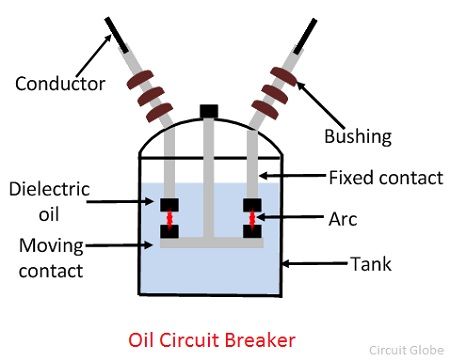
Figure 2: Old Style Oil Circuit Breaker
The important thing to understand with circuit breakers is that they are only rated to break up to a specific fault current, usually one of the R10 series (10kA, 15kA, 20kA, 25kA, 31.5kA, 40kA, etc..). if the fault current exceeds this figure, then the breaker may not succeed in extinguishing the arc and the fault will remain on the system. This would cause the upstream breakers to trip instead, potentially leading to a more sustained fault and wider loss of electrical power. It is for this reason, that it is vitally important that a short circuit study is carried out to correctly asses the rating of the circuit breakers for the system.
If you would like to know more, please contact us to discuss your project.