Power System Design
Power system design from first principles can be a daunting process. This blog has been prepared by Aurora to provide a simple, high level technical resource to describe, in simple terms, the process, rationale and criteria for designing large electrical power systems. This guide is based on practical experience and industry standard equipment and is aimed towards design engineers involved in conceptual and front-end design activities, although the principles apply to any stage of a design.
For simplicity this topic is based on UK standards and practices, and the equivalent IEC or British Standards, but the general approach is universal, although different countries can have very different design standards – particularly North America and Asia.
In basic terms, the design of the electrical power system is dictated by the plant load, its geographical distribution, the presence of any large motors, and the power generation or grid supplies available. These factors, as well as desired reliability levels, and limits of equipment ratings are primarily what govern the final design. These issues are discussed throughout this guide.
One of the important things to remember about developing a power system design is that it is not an exact process, and multiple design solutions are possible. It also often requires a certain amount of repetition and modification as new information is obtained, or client feedback is received, and it usually takes several iterations of the design process, before a settled design is finally agreed. It is important to engage the end-user early on, as they will often have their own ideas on the electrical design, and early engagement can help avoid wasted effort.
The first step on any design process is to understand the electrical load requirements. This is dictated by the number of consumers that must be supplied but should also be considered by the type of load i.e. dynamic load (motors), static load and overall system power factors and losses.
A design engineer should start the process by considering the following questions:
- How much electrical load is there?
- Is the electrical load made up of lots of small users, big users, or both?
- Where is the load geographically located?
- Are there any big motors on the network?
Load Calculation
Once these basic questions have been answered, the designer should begin the design process by starting to produce an electrical load list and a sketch of the expected power system. At this stage there is a certain amount of guesswork, as it is difficult to prepare the load list until a sketch of the power system has been prepared, and it is difficult to prepare a sketch of the power system until the load list is defined. It is usually best to start off with a block diagram showing the main electrical loads in relation to a geographic area, and to then start developing the load list from this.
Design Margin
The next key point to consider at this stage of the design is what level of design margin needs to be applied. A design margin is a multiplication factor applied to the initial load demand to cover a variety of contingencies such as uncertainty in the initial information received, expected changes that will occur during detailed design and also any planned future works. Design margins can reflect allowances for uncertainty in the design, or available information, but they can also include an allowance for planned (or unplanned) future works.
As with diversity factors, some caution should be used with design margins. If a too large margin is used this can lead to oversized and expensive equipment, if a too low design margin is used, this can mean that equipment is overloaded / undersized before it is ever brought into service. Typically recommended design margins are given below:
Voltage Levels
Once these initial questions have been considered it is time to start the design process in more detail. The first figure to be identified is the total network power load in kW (or MW), as this is the first determining factor for voltage level selection. Small power loads of 1MW or less can usually be connected to a low voltage 400V supply – but obviously depend on the local infrastructure. If the load is larger than this it is generally necessary to receive power at 11kV or above, and then to provide a distribution system and step it down to LV as required. Occasionally it is necessary to connect at 33kV (or higher), but this is usually only reserved for very large industrial or generation plants.
Where possible, it is usually best to connect at the lowest available voltage possible, this is because equipment costs rapidly increase in relation to its voltage. In addition, to the increased CAPEX, HV equipment also needs specialist design knowledge and has longer manufacturing times. A useful summary of the voltage levels, maximum power and typical maximum motor sizes is shown in the table below:
| Voltage | Plant Load | Motor Sizes | Comments |
| 400V or 415V | <2MW | <185kW | Used to supply small motors and auxiliary loads. Rarely used for generation except for very small plants. Power can only be run small distances (<500m). |
| 690V | special (<3MW) | <350kW | This is 400V configured in a different way (star wound). It is sometimes used when plant load is low, but fractionally too much for a 400V system, but avoidance of an MV system is desired. Common on offshore facilities and ships. |
| 3.3kV | 2MW to 15MW | <750KW | Rarely used as the cost is almost identical to 6.6kV. It is commonly used in conjunction with an 11kV system. |
| 6.6kV | 2MW to 30MW | 1MW to 5MW | A common voltage for small-medium sized plants. Cheap and flexible design options are possible as motors can be switched with Vacuum Contactors. |
| 11kV | 10MW to 50MW | 1MW to 10MW | A common voltage that is useful for large motors (10MW+) and distributing power over moderate distances (10-20km). More expensive than 6.6kV as motors require Circuit Breakers. |
| 20kV | 50MW to 100MW | 10MW+ via a captive transformer | An uncommon voltage but sometimes used instead of 33kV as it eliminates the need for Gas Insulated Switchgear (GIS). |
| 33kV | 50MW to 150MW | 10MW+ via a captive transformer | Used only in large plants with high power demand, or when distributing power over large distances (20km+). Main power generators will usually require step-up transformers. |
| 110kV or 132kV | 150MW to 500MW+ | N/A | Used only for the very largest facilities, design at this level requires special considerations and specialist advice. Equipment cost is increased significantly. |
Earthing and Grounding
The next step in the design process is to select the earthing method for the different voltage levels in the plant. At this point it is worth emphasizing that earthing design can become exceedingly complex, and it a detailed topic in its own right. In general Aurora would always recommend getting specialist advice in this area. Frequently the earthing configuration is pre-defined by local legislation, standards or client specifications.
Discussions on grounding and earthing (the same thing), refer to several distinct activities that are related, but in essence are all related to how the system neutral point is connected to the general mass of earth. How this is achieved will have significant impact on the system performance, system design and safety to personnel. In most electrical systems, the earthing point is usually via the star winding of the transformers in the system. So where a plant is provided with a 33/11kV step-down transformer, the transformer is usually specified as a Dyn11 vector group – where the 11kV neutral is brought out and then connected to some earthing equipment. Where star points are not available then, an artificial earth is usually installed – generally via an auxiliary zig-zag (Zn0) grounding transformer, fed from an 11kV switchboard, and used to provide an artificial ground.
Power System Configuration
Once the overall plant power demand has been calculated, load location identified, and the appropriate voltage levels determined, then development of the main power distribution system can begin. There are two main considerations regarding network configuration, the first is to decide on configuration of the main plant switchboard (often a DNO connection point) and the second is to consider the reliability and flexibility of the main power distribution system required.
The next set of considerations, are related to what kind of distribution system should be adopted. There are several different configurations to choose from, all of which offer differing levels on reliability, but as expected, also require more capital investment. Typically, the main distribution configurations are:
- Single radial feeder
- Open ring system
- Closed ring system
- Dual radial feeder
- Triple radial feeder
Radial Feeder
The simplest system is a single radial feeder; this is usually represented by a single cable from the supply source to the load center. This type of configuration is best suited to supplying loads that can tolerate a power loss without causing too much inconvenience. These would typically be used for domestic and light commercial systems or supplying single point loads. It is important to remember though, that if the cable fails, or if the upstream system fails, then there will be no power until it is repaired / restored. Single radial feeders also require the whole system to be de-energised if maintenance work is to be carried out. A sketch single line diagram is shown below:

Ring System
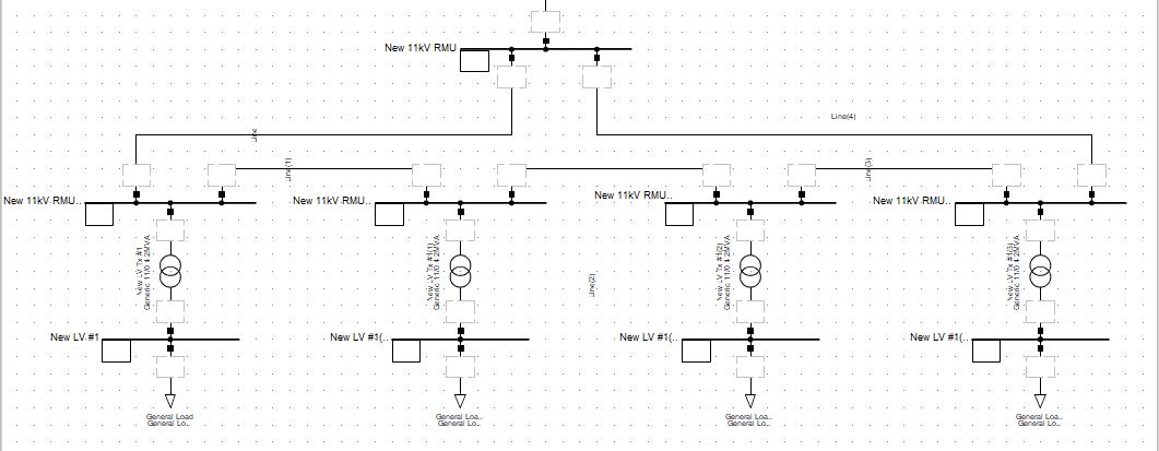
A ring system is the type most commonly encountered on HV distribution in the UK when there are several load centers supplied from one DNO supply. The system is configured in a way that there are two feeds from the main 11kV switchboard, which are routed around the site, so they form a large loop, or ring. Each of the substations has one or more transformer (or cable) feeders to local supplies, as well as two connection points to the ring, so if one of the incoming cables was to fail power could be supplied via the remaining feeder. These mini-substations are known as Ring Main Units (RMUs).
In general ring distribution system are popular in utility 11kV distribution networks, HV building services distribution systems etc., but they are less common in heavy industrial or process plants. Ring systems remain on of the most popular forms of distribution today because they are relatively cheap and have a good reliability.
There are two variations of a ring system, one where the ring is run normally closed and another where the ring is run normally open. A sketch single line diagram is shown below:
What are the limitations of ring systems? The first major limitation of any open ring feeder system, is that while they are reliable, they do not have as high level of redundancy as a dual-radial feeder that is provided with an automatic change-over facility. So, if a fault occurs on an open ring system, it will normally cause an outage that could last many minutes whilst supplies are changed over. If the ring is normally closed, then this problem is eliminated – but protection coordination becomes difficult.
Dual Radial Feeder
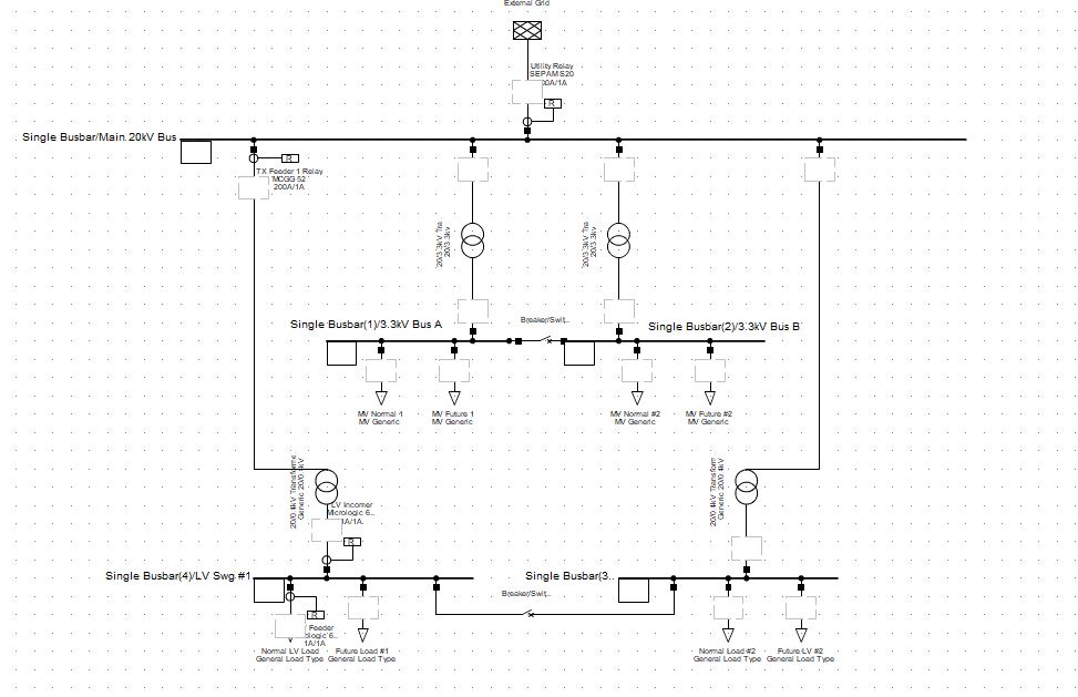
In heavy industrial plants (cement, water, oil & gas, pharmaceutical etc.) the use of dual feeders is more common than ring systems, because more loads are concentrated in one place, and the potential loss of production justifies the higher cost of dual feeders. This configuration can be used at any voltage level, and the bus-section of the supplied board can be either normally open or normally closed as detailed. A sketch single line diagram is shown below:
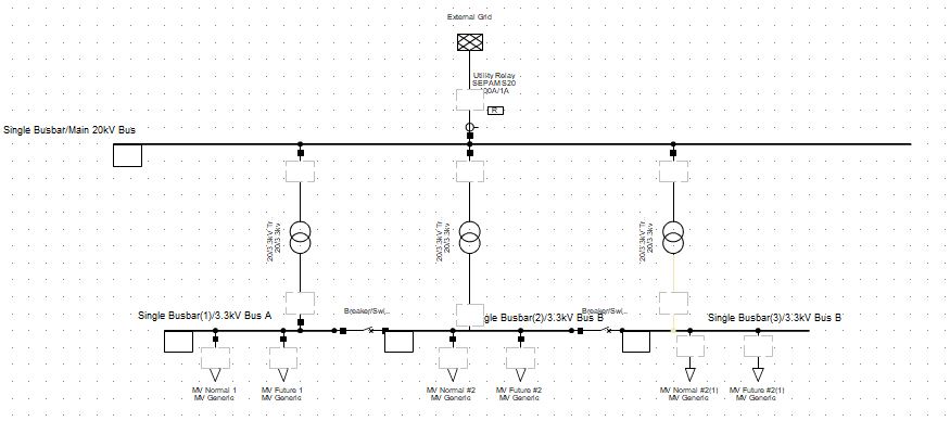
Triple Radial Feeder
This configuration is similar to the dual radial feeder above but operates on a 2 out of 3 system. The concept behind this idea is that it allows more power to be transmitted to a downstream substation; this also can increase the reliability as there is an extra level of redundancy in the supply. Occasionally larger variations of these configurations are used, where there may be 4 or more infeeds and bus-sections.
A variation of this configuration is also popular for emergency systems, where Bus A & B are treated as normal power supplies, and bus C is designated as an emergency busbar, and supplied from a diesel generator or other standby supply. Feeder C is left energised but with the circuit breaker open, and then all critical loads are then put and busbar C. Should both A and B supplies fail, then feed C is closed, and the bus section B-C tripped, leaving busbar C energized and all critical supplies in service.
A sketch single line diagram is shown below:
Power System Design – Summary
The process of power system design, can be seen as complex process, and requires consideration of a large number of factors. Some of these issues will be determined by the loads and geography of the site, others by the available utility supplies in the area and others by the level of redundancy and security required in the system. As with all things in engineering, the final decisions are a matter of trade-offs and cost optimisation. This post has only really addressed the very basics of system design up to the MV level, transmission and grid level design are significantly more complex. We hope this brief post has given some insight into the design process, and if you would like more information, or to discuss your requirement, please do not hesitate to get in touch!