A G5/4 study (also called a G5.4 study) is shorthand for the name of a standard produced by the Electrical Networks Associate (ENA) called G5/4 ‘Planning Levels For Harmonic Voltage Distortion And The Connection Of Non-Linear Equipment To Transmission Systems And Distribution Networks In The United Kingdom’.
In simple terms this means that the harmonic output of the loads to be connected to the DNO must be assessed and verified if the Total Harmonic Distortion (THD) and individual harmonic levels (up the the 50th harmonic) are within the guidelines given in the G5/4 standard.
There are two important things to note: Firstly, the allowable levels of distortion vary depending on the connection voltage – 5% THD at LV, 4% THD at 6.6kV, 11kV and 20kV, and 3% above 20kV. It should be noted that in each ‘band’ as well as the THD values being more stringent, the corresponding individual harmonics levels are also reduced – there are also additional limits at 275kv and above. Secondly, that there are three main assessment methods:
Stage 1 G5/4 Study
Stage 1 is a very simple method that states that any equipment under a certain kW (or kVA) rating may be connected without detailed assessment, in practice these limits are so low that this kind of assessment is only used by very small systems.
Stage 2 G5/4 Study
Stage 2 is the most common form of assessment, and is usually undertaken for connections at 6.6kv, 11kV and 20kV. This method requires creating of a computer model of the system to be modelled. The computer model should show the new system, with all the appropriate harmonic sources included and a simple equivalent model of the DNO utility system as an external grid. The DNO grid must be set with the correct maximum and minimum fault levels and include any background harmonic levels provided by the DNO – where these background harmonics are not know it is usual practice to assume a percentage of the G5/4 limits.
The software is then used to run a harmonic loadflow to calculate the THD and individual harmonics at the Point of Common Coupling (PCC) to check that it is compliant with the G5/4 limits.
To illustrate this, a few screenshots of a harmonic analysis are included below. Figure 1 shows part of an SLD view of the model constructed in Digsilent Powerfactory, for a small 5MW solar farm. The second figure shows the harmonic output for each individual harmonic between the 2nd and 50th harmonic for a number of different switchboards on the system, on this diagram the associated ENA G5-4 limits are also shown in the ladder boxes – it can be seen that the 5th harmonic is very high for the network, but the other harmonic values are fairly modest. The third figure shows the voltage waveform for the local 11kV busbar of the PV array – this shows a slight level of distortion, but is otherwise very close to a pure sine wave.
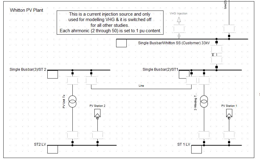
Figure 1 – Solar / PV Array Model
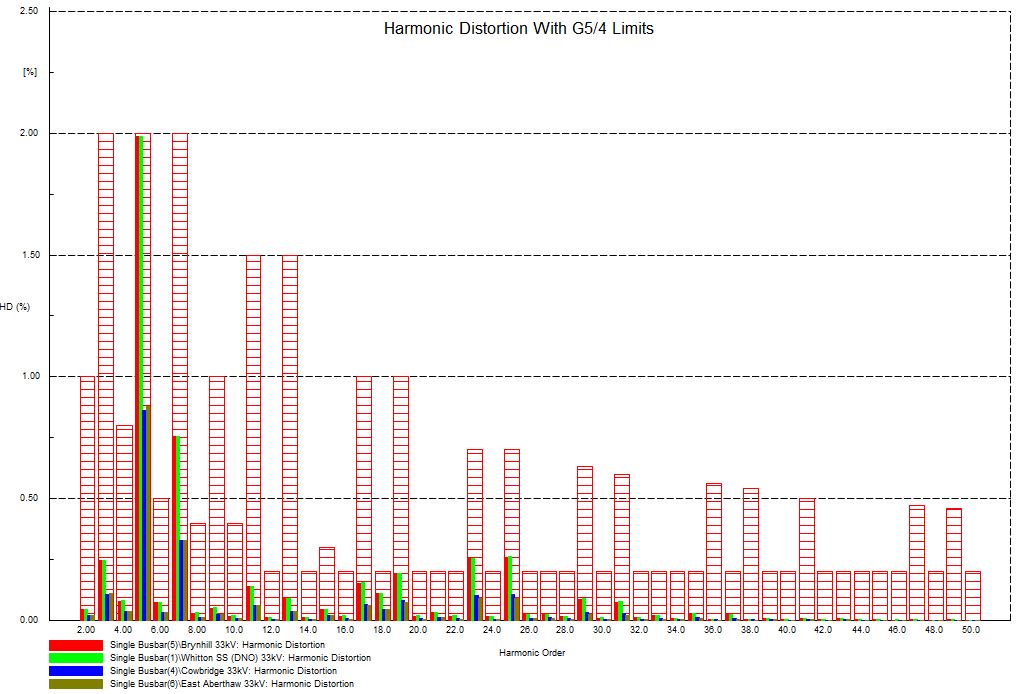
Figure 2 – Harmonic Level for Local Busbars
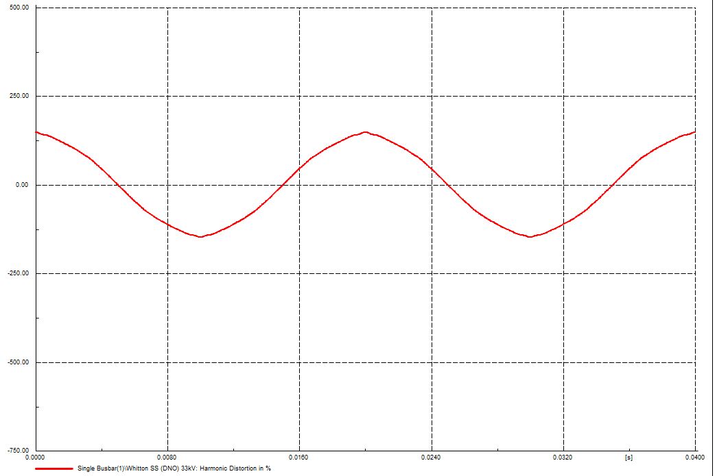
Figure 3 – Voltage Distortion at Site 11kV Busbar
Stage 3 G5/4 Study
Stage 3 assessment is much more complex than stage 2 and is undertaken when the connection voltage is 33kV or above. This method requires modelling of the nearby DNO network as well as the system to be connected. This can range from including a few local DNO substations through to modelling a large portion of the DNO network at the connection voltage as well as the voltages immediately above and below (i.e. 11kV and 132kV). Depending on the DNOs philosophy the information needed to model their network may be provided in hardcopy and modelled manually, or they may provide a copy of their own network model for import into the consultants software. It is also important to correctly model the background harmonic levels in a way that is representative of the DNO configuration.
Once the new plant and nearby system have been modelled, the system is then assessed for the THD and individual harmonics at the PCC and all nearby substations for different network loading conditions (heavy load vs light load) and outage conditions, that affect the system fault level. In addition the system must also be checked for any series or parallel resonance conditions in the network for each of the operating cases discussed previously.
The figures in the previous section are actually taken from a Stage 3 assessment, which is why several different busbars have been analysed, and only part of the model shown. The other key difference for a Stage 3 assessment is that a resonance sweep must be carried out. This is where the computer model, injects specific frequencies to observe how the network impedance behaves and to identify any sudden increases or decreases in impedance (which are characteristic of a resonance point).
An example of this this can be seen in Figure 4 below. Looking just at the 33kV results, the figure shows the bus coloured green with an increasing impedance as the harmonic number rises – this is typical for a heavily inductive load as XL= w*2*pi*f. The bus shaded light blue, shows a mild resonance around the 23rd harmonic (i.e. the impedance increases and then drops back), whilst the other buses show a fairly flat response.
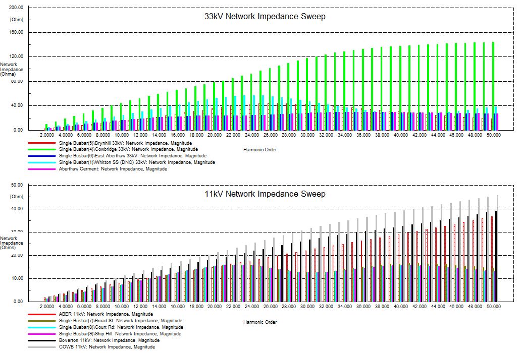
Figure 4 – Resonance Sweep of the 33kV and 11kV Network
G5/4 Limits and DNO Approval
If the THD and individual limits are met then the DNO will approve the connection. In the scenarios where the THD is within the limit, but some individual harmonics only fractionally exceeded the allowable limits then the DNO, at its discretion, my approve the connection. If the limits are exceeded significantly then the DNO will reject the connection and the harmonics must be reduced through application of harmonic filters.
Summary
It is hopefully clear from the above that a G5/4 Stage 3 assessment is far more complex than a Stage 2 assessment and will take longer to complete and is very reliant on obtaining accurate data from the DNO – which can often be the cause of delays. G5/4 studies are almost always required for connection of any new wind farms or solar farms, and while modern system design reduces the harmonic output of these systems, because of the background harmonic levels it is never guaranteed that a new plant will meet the G5/4 limits and get DNO approval without needing a harmonic filter. As always Aurora would strongly recommend carrying out these studies early, as approval by the DNO is not always guaranteed and the need for harmonic filters can add significant cost and delays to a project.