Battery Energy Storage Systems – Power Arbitrage
Part 1: Introduction
Battery Energy Storage Schemes are very versatile plants and can be used for a number of different services, depending on the plant design and aims; this can include services such as power arbitrage, voltage control, and the new Dynamic Containment (DC) service which replaces the old Enhanced Frequency Response (EFR) service. BESS units can also be used as a power balancing service, to meet shortfalls in power, to limit disturbances from the grid during transient switching events, where a plant has large dynamics loads, such as big motors and generators that switch in and out frequently.
At Aurora we have found that many developers are keen to add battery storage systems into their existing projects, but are often unsure exactly how the battery will be used. This leads to the dilemma of trying to design a system that will be flexible enough to allow future revenue streams, without pre-investing for expensive system upgrades.
This first post gives a simple guide to explain the basic ideas of how a BESS works and looks at their role in providing power arbitrage.
Part 2: BESS Basics
Before we get into the specifics, it is worth covering a couple of basic ideas of what a BESS is and how it operates. First off, the term BESS is generic name for an electronic Power Conversion System (PCS) i.e. inverter, coupled with some form of battery. From the DNO and TSO perspective the battery doesn’t actually matter too much, and it is the PCS that is really of interest. The battery can be anything from old car batteries, to modern li-Ion batteries, or more advanced cryo-batteries or flow batteries. The battery type just determines how much energy can be stored and how quickly it can be converted from chemical form to electrical energy.
Second, a simple concept that is often misunderstood is the difference between power (MW) and energy (MWh). A BESS rated at 1MW & 1MWh can provide 1MW for an hour, of 0.5MW for 2 hours, or 0.25MW for 4 hours etc. but it can never provide more than 1MW, because this limit is imposed by the inverter rating and system design. From the DNO perspective the amount of MW is important, as this governs the main power flows in their network.
This leads to our third point, which is that of power swings. Simple MW flow is easy to understand from DNOs heat maps, but the ability of the DNO network to cope with large power swings is much less clear and usually needs some analysis. For power swing, we are referring to the speed at which the BESS needs to change from import to export and vice versa. For power arbitrage this is very slow and doesn’t cause a significant power swing, but for fast response services like DC, the power swing can be significant with a 50MW BESS, potentially going from full export to full import in 1s, giving a 100MW/s power swing – which would challenge the most robust of power systems. This is why the G99 forms ask for the ramp rate of the BESS. This is bit of a tricky area, and often a major constraint, which we will go through in another post.
Our third point is that a BESS can provide reactive power as well as providing active power, and importantly it can provide reactive power at the same time, which is useful for regulating voltage on the DNO network. Provided the BESS is correctly sized, it could easily provide 20MW of active power and 20MVAr of reactive power.
So, when preparing a grid application for a BESS it is important to understand what services we are hoping to provide to the system and what the local limitations are. The DNO or National Grid, typically want to know the MW capacity of the site, and the worst-case power swing as well as any reactive power flow capability, as these are what will affect their system behaviour and responses, but are not usually that interested in the MWh rating of the system.
Part 3: Power Arbitrage
The power arbitrage service of a BESS is technically and commercially the simplest concept for battery storage. It is based on the simple premise of absorbing energy when it power is cheap, such as at night or when there is excess power from CHP or solar array, and then discharging the battery during peak load times. The benefit of such an approach allows what is known as load demand curve shifting, where the excess power from renewables (often solar) is stored at high production times / low demand then discharged at low production times / peak demand. This has two main benefits. Firstly, and depending on the profile, high tariff electricity costs can be avoided, and a flat charging profile created. Secondly, it means that the size of the grid connection can potentially be reduced, although one needs to consider what happens if there was a shortfall in the surplus power i.e. a very cloud day, if the surplus comes from a Solar PV array.
The revenue streams here are obviously limited to the cost of energy creation and storage at cheap times, compared to the cost of energy during high tariff times, and is based on the concept of peak shifting the energy demand, so that it is balanced more evenly across a 24 hour (or whatever other timeframe). In the authors opinion, this is the ‘holy grail’ of most BESS units and The System Operators (TSO), an electrical system demand that is predictable, and therefore easy to plant and dispatch. In practice to achieve, this the BESS has to be cheap and robust enough to store and dispatch energy as needed, and when is most economic to do so.
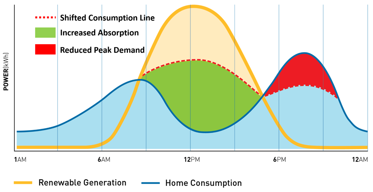
Figure 1: Diagram Showing Power Arbitrage Concept
With power arbitrage, the charge and discharge of the BESS is usually very slow, and this will not overly stress the host electrical system or the DNO system. From a design point of view, compliance with the ENA P28/2 standard is not usually an issue, but a large battery systems can contribute significantly to the system harmonics and voltage flicker due to the power electronics operation, which usually needs some careful analysis to ensure compliance.
A less obvious use of a BESS is using it as a power store to support starting and operation of a heavy consumer of power. Let us say for example you have a heavy industrial plant that you want to add a new 10MW motor to. Starting these motors is always a complex process, but fortunately ones that a Variable speed Drive solves easily, but what happens if your grid supply to the DNO is maxed out and an upgrade will cost millions. Simple(ish), you install a BESS and charge it up overnight, then discharge it when the new drive needs to operate. The DNO does not see any additional power demand and no network upgrades are needed.
Part 4: Applications – Power Arbitrage & Balancing in a Water Treatment Works (WTW)
For an application example, let us consider an example of a Water Treatment Works (WTW) that is hoping to achieve carbon neutral status within the next 5 years. WTW sites are interesting ones to study, as they tend to have a mix of large varying loads such as pumps and compressors, and plenty of space to install Solar PV and a BESS and carry out the tie-ins between the new and existing plant. It should be noted that for our analysis, the site type doesn’t really matter as the principles are the same.
So how does power arbitrage work with a battery storage system work? This is best understood with an example. First, we start with the basic premise, that the plant owner has assessed their DNO connection and there are no problem and second that site has enough space to install a fair sized Solar PV array of 5-10 MW. Next, we look at the site power consumption, this is usually very dynamic, but lets pretend for a moment, that we can simplify things a bit and say they have an average steady state consumption during the day of 2MW, and at night-time it drops to 0.5MW. Our basic specification might look something like this:
- Space to install 5-10MW Solar PV array.
- Available HV point for tie-in.
- Desire to achieve full carbon neutral operation.
- Site load profile is simplified to a consistent value of:
- 2 MW approximately constant load between 8am and 7pm (11 hours) = 22MWh
- 5MW constant load between 7pm and 8 am (13 hours) = 6.5MWh
Simple deployment of a solar PV scheme would certainly help the asset owner, as the power produced by the Solar PV would offset the power consumption of the WTW by a significant margin. However, the problem would be that either the Solar PV would be oversized and during peak daylight hours would be exporting power, or it would be undersized, and not fully offset the power demand, and in both cases the night-time power demand would still be needed. This presents a dilemma for the asset owner, as neither scheme meets the objectives, but by adding a BESS into the mix, we can possible meet all the target goals.
Next, let’s do bit of basic maths to see what works, to calculate average any usage, energy storage capacity and so on. This can be done in a number of ways, depending on the level of sophistication desired, at the most basic, a simple Excel and graphical model can be generated of the load and generation profiles, but it is relatively easy to create more advanced mathematical models of the system, using various integration methods and piecewise linear functions, or directly in simulation package like Matlab. For the purpose of this post we will go for an easy Excel approach.
In the below diagram we can see a simplified power generation diagram shown in block format for the power generation (green), power demand (red), excess PV discharged into the BESS (blue) and power discharged from the BESS (yellow).
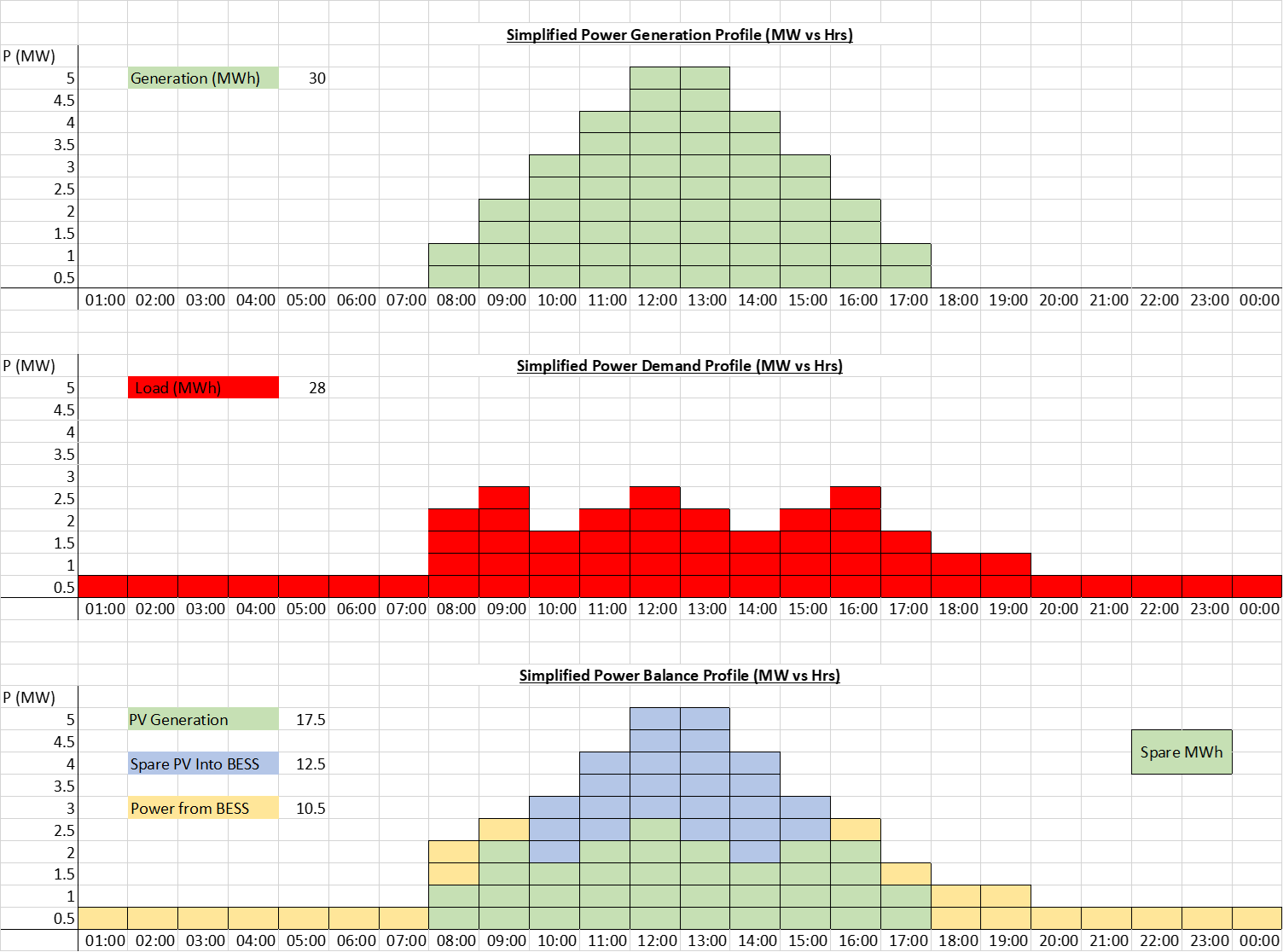
Figure 2: Simplified Block Diagram Showing Power Arbitrage Calculation
From the above plots we can see that we get a pretty good power balance, with around 2MWh spare capacity from the Solar PV system, which we can account for with intermittency, shading and other losses. We do can do some more simple maths and we can roughly dimension our PCS and battery size, as follows:
- The solar PV is sized to give a peak output of 5MWac.
- The battery PCS size has to be equal to the largest difference between the plant demand and the solar output. This occurs in the evening when power demand is still high and the solar output has fallen to near zero . I.e so the delta is 1 MW.
- We can see from the above that we need the BESS to be able to deliver 10.5 MWh.
- Our final design is therefore a 5 MW PV array coupled with a 1 MW BESS with a 10.5 MWh energy store.
Part 5: Summary – Power Arbitrage
The above is obviously very simple analysis, representing a simple Solar PV curve, and not accounting for probability and differing irradiance levels during the day and seasons. Likewise, the load is likely to significantly more variable than the simplified model shown. The thing to remember here, is that the post just shows a simple model for demonstration purposes, to show a principle of how a system could be made to work.
In practice, it is usually not economic to design a Solar PV and BESS system that achieves full carbon offset, because of the inherent probabilistic values in the irradiance levels. However, with some careful analysis and a bit of time, a Solar PV and BESS can go along way to meeting this target. The above example is for a WTW but would work just as well, for a large factory, or country estate. Of course, adding in a BESS to a brownfield site is never quite that simple, so it is usually necessary to carry out some surveys, and identify if the equipment is suitably rated for the increased duty and then identify the necessary tie in location.
It should also of course be noted that we have considered Solar PV and a battery storage solution here, but the principle applies to any intermittent renewable, such as wind power or wave power and any other storage technology, such as hydro, compressed air / gas etc. One final thing we can do with the new system, is to run the Solar and BESS at a slightly lagging power factor (producing MVArs) so the site is held at unity PF and even greater savings are achieved. If you would like to discuss your project requirements, please get in touch.
I will post some subsequent articles on battery storage systems, and dynamic containment and managing P28/2 compliance, as well as MVAr / Voltage Control early next week!
[1] Apologies to whoever generated this image, I found it online a while and thought it was a good example. If you are the owner, please drop me a line and I will add in a credit.